Digital/power connector, Control signal specification, Ttl level uart interface – ThingMagic M6e User Manual
Page 25: Control signal specification 25
Hardware Interfaces
A D I V I S I O N O F T R I M B L E
Hardware Overview
25
Digital/Power Connector
The digital connector provides power, serial communications signals, shutdown and reset
signals to the M6e module, and access to the GPIO inputs and outputs. These signals are
provided through connector part number: Molex 53261-1571 - 1.25mm pin centers, 1 amp
per pin rating. which mates with Molex housing p/n 51021-1500 with crimps p/n 63811-
0300
. See
for more information on typical cable parts.
Control Signal Specification
TTL Level UART Interface
The module communicates to a host processor via a TTL logic level UART serial port or
via a USB port. Both ports are accessed on the 15-pin
. The TTL
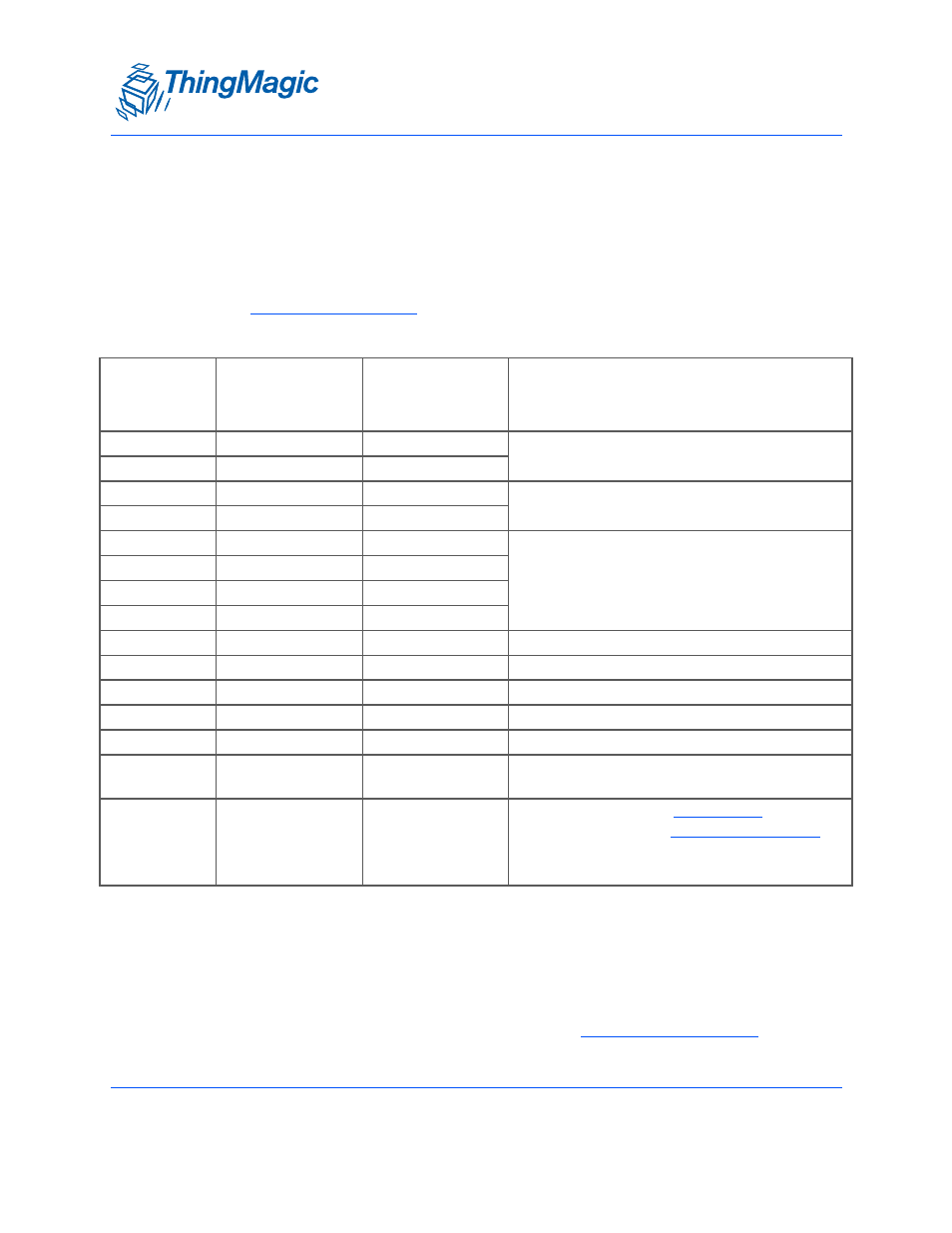
M6e Digital Connector Signal Definition
Molex
53261-1571
Pin Number
Signal
Signal
Direction
(In/Out of M6e)
Notes
1
GND
P/S Return
Must connect both GND pins to ground
2
GND
P/S Return
3
+5VDC
P/S Input
Must connect both 5V supplies
4
+5 VDC
P/S Input
5
GPIO1
Bi-directional
Input 5VDC tolerant, 16mA Source/Sink
6
GPIO2
Bi-directional
7
GPIO3
Bi-directional
8
GPIO4
Bi-directional
9
UART_RX_TTL
In
In (Pull-down with +10k Ohm to Ground)
10
UART_TX_TTL
Out
Out
11
USB_DM
Bi-directional
USB Data (D-) signal
12
USB_DP
Bi-directional
USB Data (D+) signal
13
USB_5VSENSE
In
Input 5V to tell module to talk on USB
14
SHUTDOWN
In
Pull LOW to enable module. Set HIGH to dis-
able all 5V Inputs and shutdown module.
15
RESET
Bi-directional
HIGH output indicates
is running
LOW output indicates
running
Note:
Not 5V tolerant.