Tjernlund, Cop2 system wiring, Warning – Tjernlund COP2 Constant Operating Pressure Exhaust Control 8504208 User Manual
Page 7: Option 1 option 2 option 3, Option 4, Low voltage = 115 vac, Legend, Vfd will result
6
N
L1
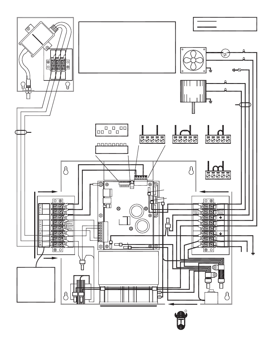
COP2 SYSTEM WIRING
POWER SUPPLY
115 VAC
GROUND
WHT
BLK
RED
WHT / RED
COOLING FAN
EXHAUSTER
MOTOR
FIGURE
GRY
GRY
VIO
YEL
RED
V+
COM
1-10
P2
P1
C2
C1
RED
GRN
WHT
BLK
L1
N
WHT
5
1
1
I
N
GRN
WHT
BLK
RED
BLK
U
A
S
H
T
X
E
E
R
GRN
GRN
1-10
COM
V+
VIO
YEL
RED
controller
1
2
3
4
5
6
7
8
RED = FAULT
GREEN = OK
FRONT VIEW
TOP VIEW
LED1
LED2
RED = FAULT
GREEN = OK
Z B A
GND
3.3V
Z B A
GND
3.3V
Z B A
G
ND
3.3V
OPTION 1
OPTION 2
OPTION 3
OFF
ON
DIP SWITCHES
OUT = ON, IN = OFF
Z B A
G
ND
3.
3V
OPTION 4
EXHAUSTER
THERMOSTAT
RED
= LOW VOLTAGE
= 115 VAC
G
N
L
TB6
TB5
LEGEND
PSC OR SP
VFD
ON / OFF
R
TJERNLUND
WARNING
Do not use the COP2 with gas or oil fired heating
equipment without interlocking all burners being
served with a CIC1 Interlock Control and the
required number of MAC-Series Multiple
Appliance Controllers. The interlock feature is not
activated unless a jumper is installed as shown in
OPTION 3 or 4 below.
OPTION 1:
OPTION 2:
OPTION 3:
OPTION 4:
Exhaust Only
Exhaust Only,
Exhaust with CIC1 Interlock
Exhaust with CIC1 Interlock,
No Overdraft Fault
No Overdraft Fault
115 VAC +/- 10%, 47-64 Hz, Single Phase, 8.0 Amps maximum
115 VAC +/- 10%, 0-60 Hz, Single Phase, 0.12 - 6.2 Amps
Over-Temperature and Over-Current Protected.
For use only with approved Tjernlund Products, Inc. model fans.
800.255.4208 www.tjernlund.com
IF APPLICABLE
WHT
BLK
WHT / RED
Terminals.
DO NOT supply
power to them or
damage to the
TRANSDUCER
Output:
Input:
These are Signal
8052082
6-3-14
PART
1303907
VFD will result.
MAX.
LENGTH
MAX.
LENGTH
100 FT.
250 FT.