Symtech VFX 1 User Manual
Page 18
17
Empty Used Coolant
1)
Verify all control panel valves are in neutral position, and flow control
valves at hose ends are OFF.
2)
Connect to clean shop air supply (70-120psi).
3)
Turn AIR CONTROL valve (#1) and FUNCTION CONTROL valve (#2) to
the left EMPTY USED (
PURPLE
) and FLUID CONTROL valve (#3) to the
right, EMPTY USED (
PURPLE
).
4)
Connect cone assembly to BLACK/USED coolant flow control valve at hose
end. (Fig 3)
5)
Secure cone assembly into used coolant storage vessel. SLOWLY open
BLACK/USED coolant flow control valve.
6)
Close BLACK/USED coolant flow control valve at hose end when all used
coolant drains from unit.
7)
Return all control panel valves to neutral position. (Fig 4)
Empty Tool Storage compartment Waste Fluid Reservoir
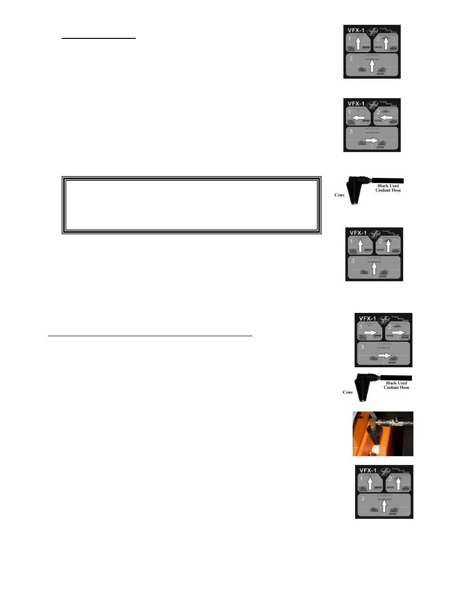
1)
Connect clean shop air supply (70-120psi).
2)
Turn
AIR CONTROL
valve (#1), FUNCTION CONTROL valve (#2), and
FLUID CONTROL
Valve (#3) to the right LOWER LEVEL (
YELLOW
)
.
Vacuum will begin to build on the compound gauge. (Fig 1)
3)
Connect extraction cone to BLACK/USED coolant flow control valve.
(Fig 2)
4)
Insert extraction cone over tool storage compartment waste fluid
reservoir tube and remove all used coolant from reservoir. (Fig 3)
5)
Open BLACK/USED coolant flow control valve at hose end.
6)
When used coolant flow ceases, close used coolant flow control valve at hose
end.
7)
Return all control panel valves to correct neutral position, (Fig 4) and
flow control valves at hose ends to off.
Note: The unit uses regulated air pressure (up to 30psi) to empty
the used coolant from the unit. Once the used fluid has been
expelled, the air pressure will cause the BLACK/USED
coolant hose to “jump” or “jerk. Properly secure the hose to
prevent spills.
Figure 1
Figure 2
Figure 3
Figure 4
Figure 1
Figure 2
Figure 3
Figure 4