Symtech VFX 1 User Manual
Page 17
16
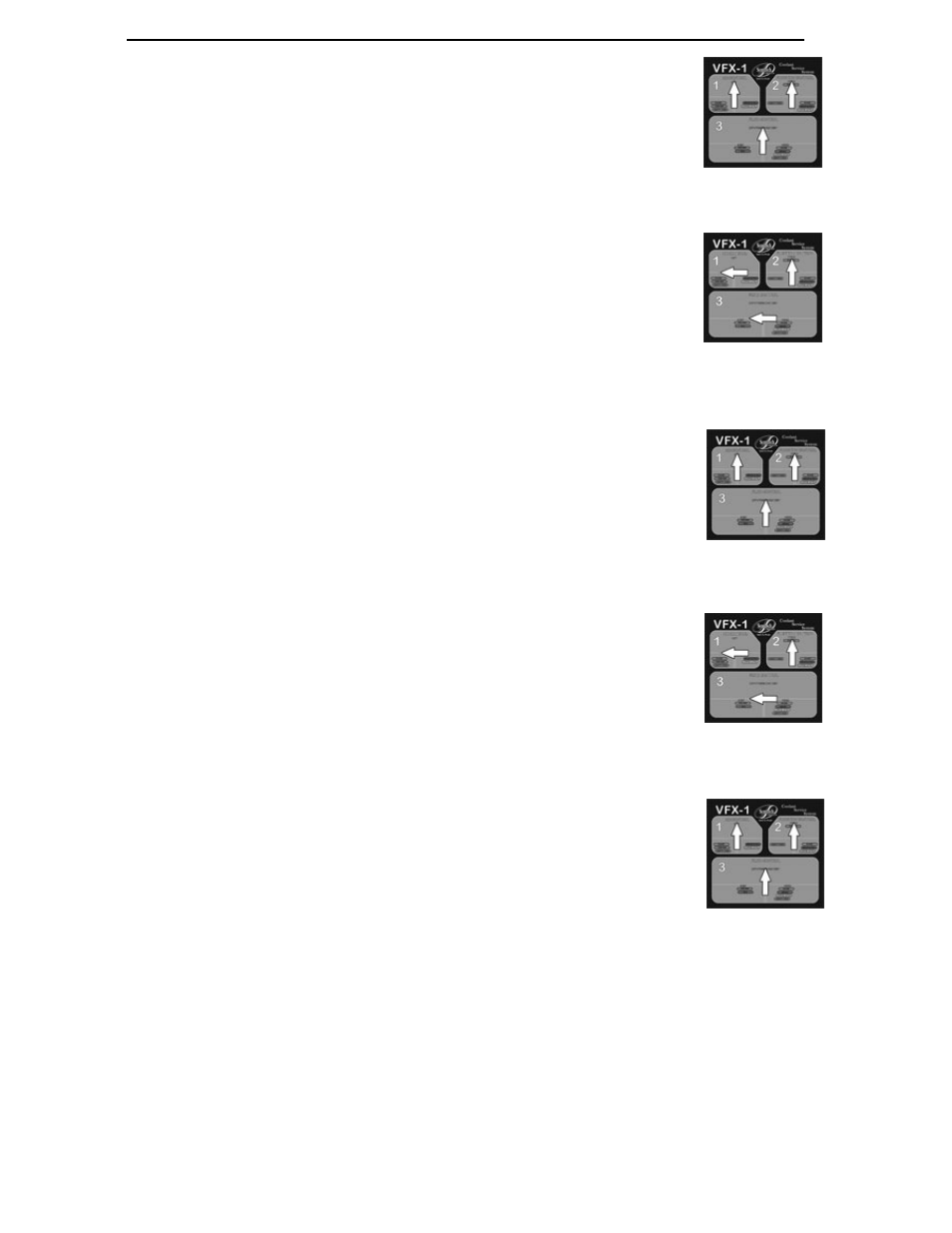
Changeover of ALTERNATE (external) Coolant Tank to PRIMARY (internal) Coolant Tank
1)
Verify all control panel valves are in neutral position, (Fig 1) and
flow control valves at hose ends are OFF.
2)
Connect to clean shop air (70-120psi).
3)
Romove lid from ALTERNATE (external) coolant tank and connect to
ALTERNATE (external) coolant tank hose.
4)
Turn Coolant select valve to ALTERNATE (external) Coolant Tank.
5)
Turn AIR CONTROL valve (#1) and FLUID CONTROL valve
(#3) to the left, TOP OFF (
GREEN
). (Fig 2)
6)
Connect vacuum cone assembly to RED/NEW coolant flow
control valve at hose end.
7)
Place vacuum cone into ALTERNATE (external) coolant fluid
tank, SLOWLY open RED/NEW coolant flow control valve at
hose end.
8)
Close RED/NEW coolant flow control valve at hose end when all coolant has
been purged from unit.
9)
Return all control panel valves to neutral position. (Fig 3)
10)
Replace lid on ALTERNATE (external) Tank and store for future use.
11)
Turn AIR CONTROL valve (#1) and FLUID CONTROL valve (#3) to the left,
TOP OFF (
GREEN
). (Fig 4)
12)
Place cone assembly still connected to RED/NEW coolant flow control valve
into tool storage compartment at front of machine, or waist fluid container.
SLOWLY Open RED/NEW coolant flow control valve at hose end.
13)
Close RED/NEW coolant flow control valve at hose end when air has been
purged from line or a steady stream of coolant from PRIMARY (internal) coolant
tank flows from unit.
14)
Return all control panel valves to neutral position. (Fig 5)
15)
Unit is now ready to perform coolant system service with PRIMARY (internal)
Tank coolant.
Figure 3
Figure 2
Figure 1
Figure 5
Figure 4