Celllog 8s connection diagram, Cell voltage monitor & logger celllog 8s, External controls and connections – ProgressiveRC 8S CellLog User Manual
Page 4
-4-
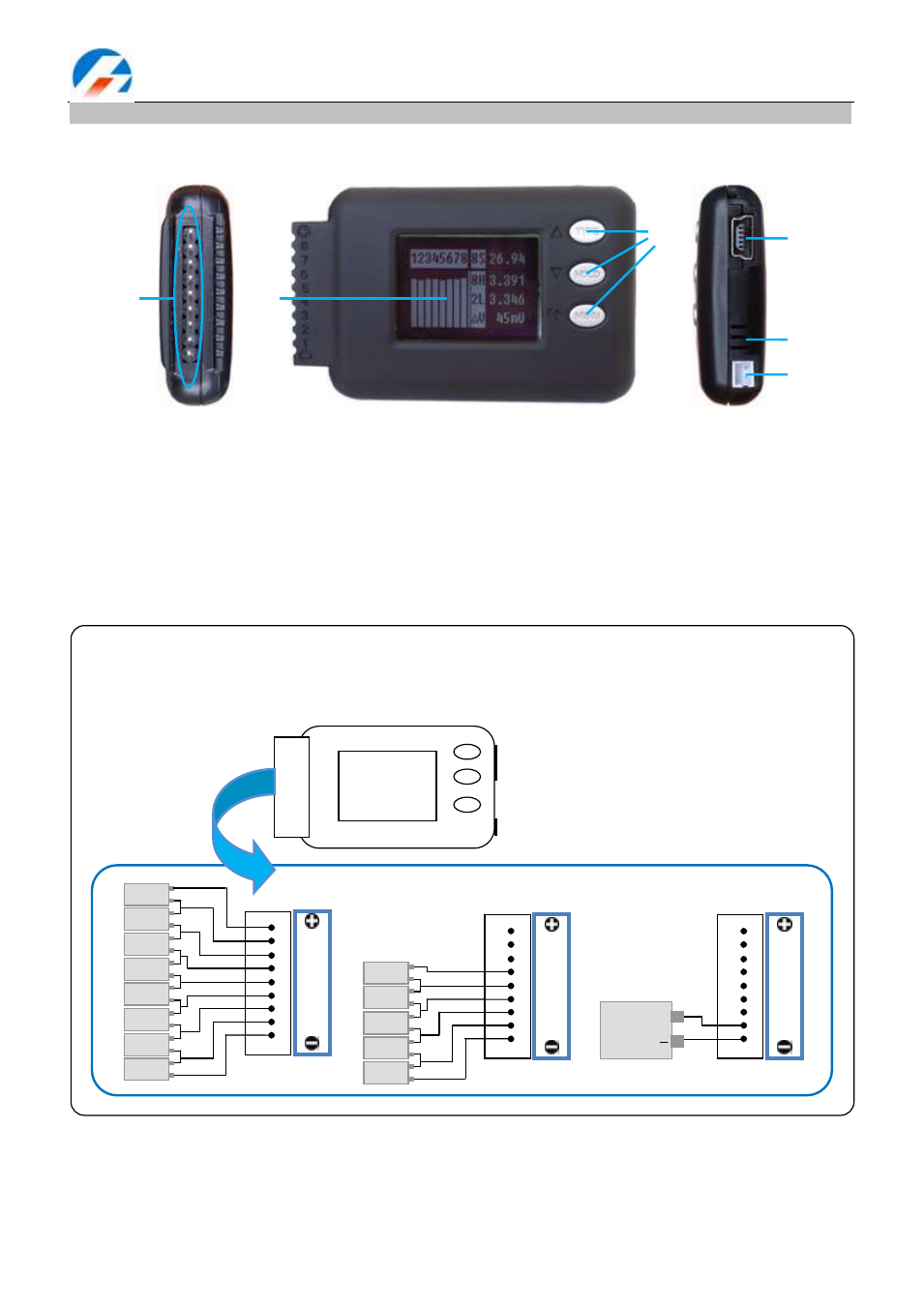
Cell Voltage Monitor & Logger CellLog 8S
External controls and connections
1. Input plug 2. LCD screen 3. Function button 4. USB port 5. Beep 6. Alarm port
①
②
③
④
⑤
⑥
+
8
7
6
5
4
3
2
1
-
TYPE
HOLD
MENU
PIN 1
PIN 9
8
7
6
5
4
3
2
1
1S
+
-
2S
+
-
3S
+
-
4S
+
-
5S
+
-
6S
+
-
7S
+
-
8S
+
-
PIN 1
PIN 9
8
7
6
5
4
3
2
1
1S
+
-
2S
+
-
3S
+
-
4S
+
-
5S
+
-
PIN 1
PIN 9
8
7
6
5
4
3
2
1
BATT.
PACK
(4—43V)
+
CellLog 8S Connection Diagram