Caution, Additional refrigerant charge 7.2, Drain piping – Pridiom Cassettes PCM183HX Installation Manual User Manual
Page 18
17
installation manual
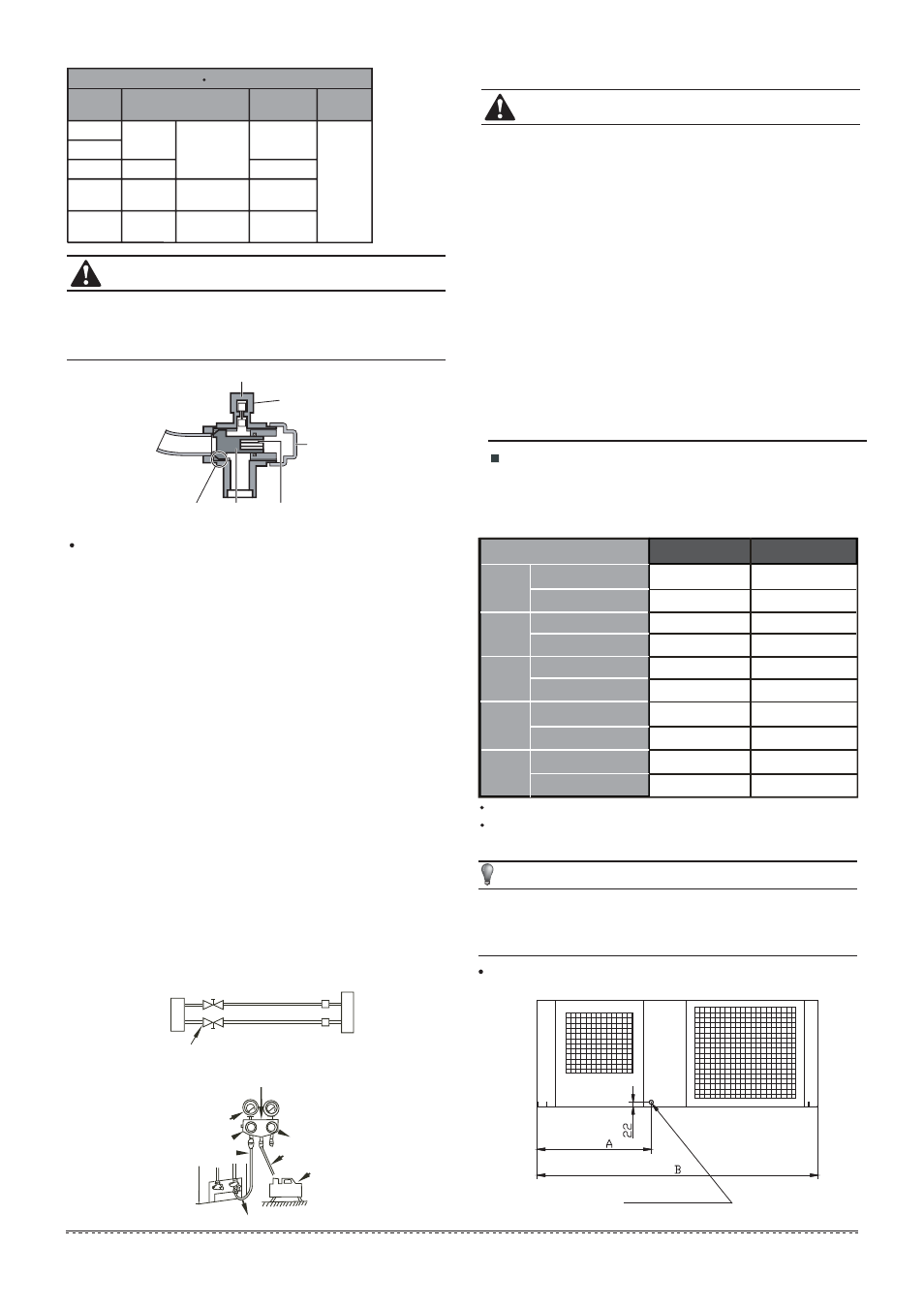
Drain Piping
Fig.7-10
1
2
4
3
5
6
Fig.7-9
Using the vacuum pump
Loosen and remove the maintenance nuts of stop valves A
and B, and connect the charge hose of the manifold valve to
the service port of stop valve A. (Be sure that stop valves A
and B are both closed)
Connect the joint of the charge hose with the vacuum pump.
Open the Lo-lever of the manifold value completely.
Turn on the vacuum pump. At the beginning of pumping,
loosen the maintenance nut of stop valve B a little to check
whether the air comes in (the sound of the pump changes,
and the indicator of compound meter turns below zero). Then
fasten the maintenace nut.
When the pumping has finished, close the Lo-lever of the
manifold valve completely and turn off the vacuum
pump.Make pumping for 15 minutes or more and check that
the compound meter indicates -76cmHg(-1X10 Pa)
Loosen and remove the cap of stop valves A and B to open
stop valve A and B completely, then fasten the cap.
Disassemble the charge hose from the service port of stop
valve A, and fasten the nut.
5
7
Fig.7-8
Fig.7-7
service port
cap
maintenance nut
Stop valve
Gas side
Liquid side
hexagon hole
shaft
seal
Outdoor
unit
Indoor
unit
A
C
D
B
Pressure meter
Multi-meter
-76 cmHg
Lo-lever
Lo-lever
Charge hose
Charge hose
Vacuum pump
Hi-lever
Manifold valve
Always use a charge hose for service port connection.
After tightening the cap, check that no refrigerant leaks
arepresent.
Table 7-3
CAUTION
Tightening torque N M (Turn clockwise to close)
Stop
Valve size
Shaft (valve body)
Cap
(Valve lid)
Ø6.4
Hexagonal
wrench 4 mm
Ш9.5
Ш12.7
Ш15.9
Hexagonal
wrench 6 mm
Hexagonal
wrench 6 mm
Ø19.1
Maintenance nut
35~40
23~27
18~22
13.5~16.5
5~7
7~9
9~11
11~13
11.5~13.9
Additional Refrigerant Charge
7.2
Refrigerant cannot be charged until field wiring has been
completed.
Refrigerant may only be charged after performing the leak
test and the vacuum pumping.
When charging a system, care shall be taken that its
maximum permissible charge is never exceeded, in view of
the danger of liquid hammer.
Charging with an unsuitable substance may cause
explosions and accidents, so always ensure that the
appropriate refrigerant is charged.
NOTE
CAUTION
If a negative result is gotten for R from Table 7-4, no
refrigerant needs to be added nor removed.
Additional refrigerant will be twice of R from Table 7-4 if
the indoor unit installed throttle assembly.
Outdoor unit is equiped with a drain piping. Its position is
shown figure below.
The outdoor unit is factory charged with refrigerant. Calculate
the added refrigerant according to the diameter and the
length of the liquid side pipe of the outdoor unit/indoor unit
connection.
Refrigerant containers shall be opened slowly.
Always use protective gloves and protect your eyes when
charging refrigerant.
Table 7-2
Brass tube(mm)
R410A R22
Ш6.35
Ш9.53
Ш12.7
Ш15.9
Ш19.0
0.022kg/m×(L-5)
0.011kg/m×(L-5)
0.060kg/m×(L-5)
0.030kg/m×(L-5)
0.110kg/m×(L-5)
0.060kg/m×(L-5)
0.170kg/m×(L-5)
0.085kg/m×(L-5)
0.250kg/m×(L-5)
0.125kg/m×(L-5)
0.030kg/m×(L-5)
0.015kg/m×L
0.065kg/m×(L-5)
0.030kg/m×L
0.115kg/m×(L-5)
0.060kg/m×L
0.190kg/m×(L-5)
0.095kg/m×L
0.290kg/m×(L-5)
0.145kg/m×L
orifice in the indoorunit
orifice in the outdoorunit
orifice in the outdoorunit
orifice in the outdoorunit
orifice in the outdoorunit
orifice in the outdoorunit
orifice in the indoorunit
orifice in the indoorunit
orifice in the indoorunit
orifice in the indoorunit
NOTE:The number of bends is up to the length of the max
height drop.Usually for each 10m need a bend.
NOTE:the table above refer to the liquid tube.