Slide 4 – Origin Live Power Supply Upgrade User Manual
Page 4
5.
On the transformer circuitboard disconnect the
two wires shown. The colours of these vary
between generations, so yours may not match the
image. Each cable should be marked “SW” (for
switch) on the board. These can be either
desoldered from the underside or cut close to the
the board and then 6mm stripped off the end.
6.
If the DC lead has a grommet attached, simply
cut this off, then feed the long DC lead of the
Origin Live power supply from underneath the
turntable up through the hole located towards the
rear of the unit.
Tie a simple overhand knot approx 6 inches
(150mm) from the wire end to prevent the cable
being pulled back out of the deck through the hole.
7.
Connect the supplied terminal block to the
disconnected switch leads.
Connect the positive wire of the DC lead (white
stripe) to the opposite side of the terminal block.
Connect the SHORT lead to the same side as the
DC lead. It does not matter which way round the
DC and SHORT lead are.
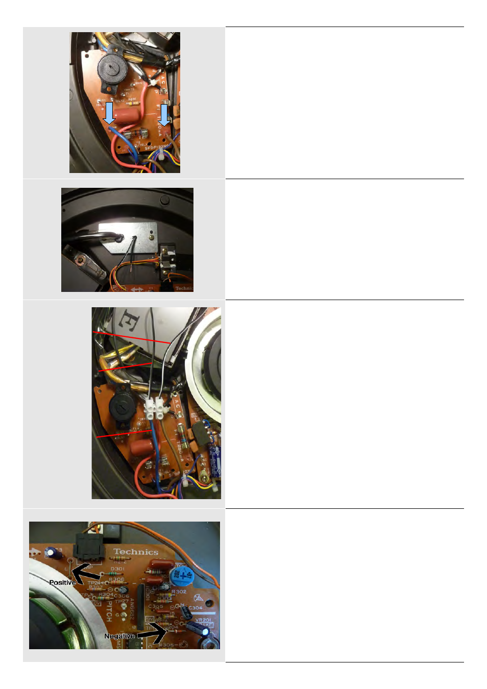
8.
Solder the other end of the SHORT lead to the
wire link labeled J. This is marked positive in the
image.
Solder the DC lead negative (all black) wire to the
left hand side of diode D204.
If your board is different to the one shown please
contact us.
Completed image over page.
Switch leads
Long DC lead
(Positive wire)
Short lead