Install-center door-w-ohcc, Figure 1 figure 2 figure 3 – Oldcastle BuildingEnvelope Thermal Clad Door and Frame User Manual
Page 21
INSTALLATION OF CENTER HUNG DOOR WITH
STANDARD CONCEALED CLOSER
D O O R A N D F R A M E
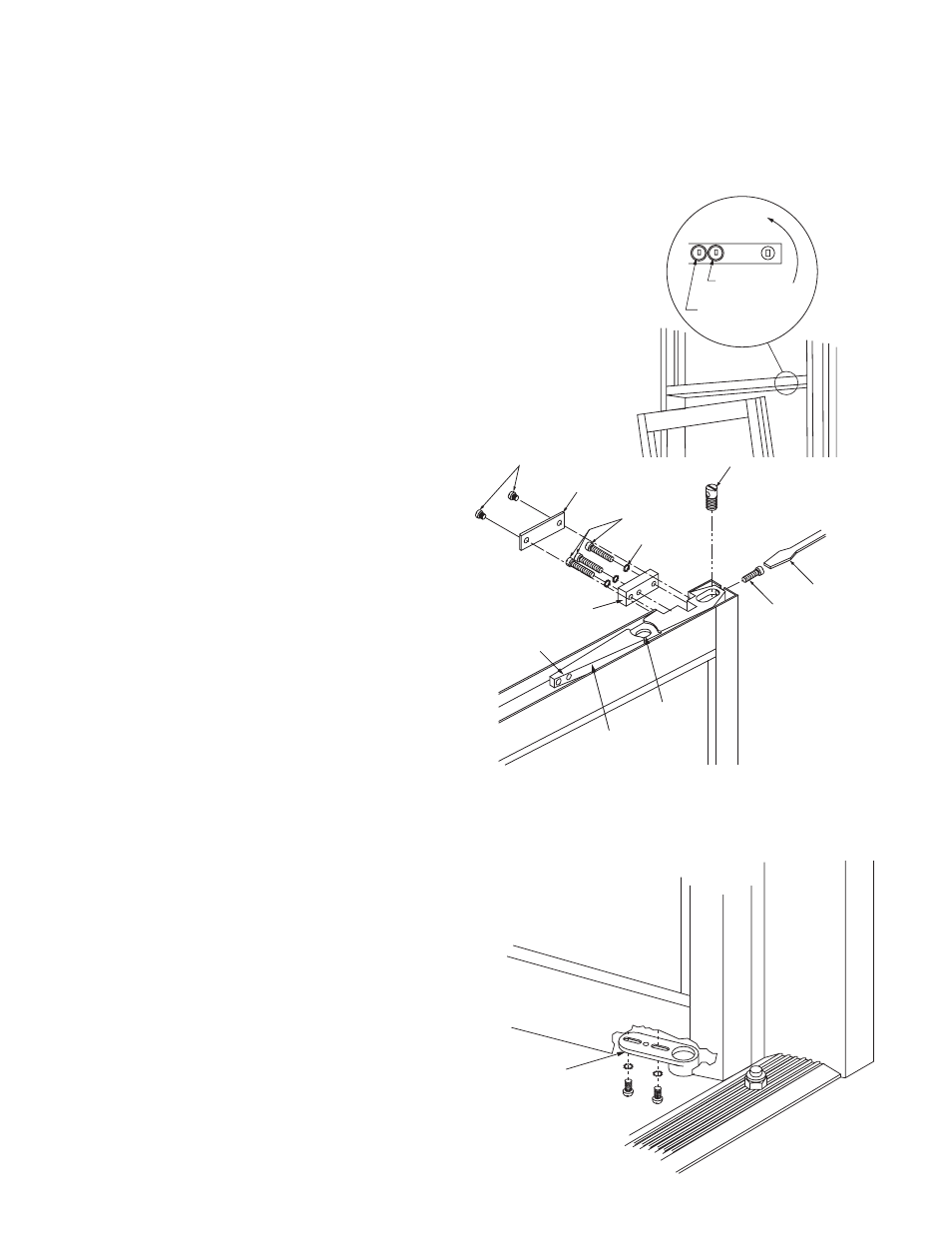
1. With closer mounted in transom, (see Frame
instructions) make sure it is in hold-open position.
When closer has no hold-open feature, the follow-
ing “dogging” method applies:
A. Rotate closer spindle to 90º (either R.H. or
L.H.) with a wrench for door installation, or
rotate with door, when removing closer from
existing installation.
B. Insert suitable 5/32" diameter hard pin or nail
through 3/16" hole in base plate (located on
direct line between pivot and pivot jamb) (See
fig. 1)
C. The pin should go through base plate, lower
bushing plate at closer and hole in dogging
cam (some back and forth movement of door
or wrench may be necessary to locate this
hole. The pin should be inserted at least 1
1/2" into closer.
D. Holding the pin in place, release door or
wrench gently. Closer will be held at 90º.
2. Lift door onto floor pivot making sure of pin
engagement. Place door upright in the 90º open
position corresponding to the position of the indi-
cator mark on the closer shaft.
3. Push top arm of door against closer shaft.
4. Apply top clamping block per label at top of door,
with two socket head cap screws using 7/32" hex
key, but do not tighten (See fig. 2).
NOTE: If vertical adjustment of the door is required,
use a wrench to turn bottom pivot adjusting screw up
or down (See fig. 3).
CAUTION: Make sure top clamping block screws are
loose before making adjustment.
5. Return to top clamping block and TIGHTEN sock-
et head cap screws SECURELY and EVENLY per
the torque label on the top corner of door.
CAUTION: Be sure to remove pin before trying to
operate closer. To remove pin, open closer from
dogged position slightly to remove spring force
from pin. Remove pin and gently release closer.
6. Insert weathered end trim cap at top and secure
to door with screw.
7. To operate, push door out of hold open position.
(If model has no hold open, remove dogging pin
and gently release closer.)
8. Glaze door. (See page 15)
9. Check top arm centering screws for snug contact
with the sides of the top rail.
CAUTION: Over-tightening will bulge the top rail.
Check tightness of arm anchoring screws.
If the door does not center in the frame after
being operated a few times, loosen the top arm
anchor screws, readjust the centering screws (do
not bulge sides of top rail) and retighten the
anchor screws.
10. Adjust closer closing speeds and latching speeds.
(See Adjustment Instructions packed with Closer.)
Figure 1
Figure 2
Figure 3
Adjust door by turning adjusting
screw clockwise to lower door
or counterclockwise to raise
door. When proper setting is
achieved tighten top arm
attachment screws.
CLOSING
SPEED SLOW
LATCHING
SPEED
FAST
*PLATE SCREW
*DRESS PLATE
*LOCK WASHER
*ARM STUD
*ARM CLAMPING SCREW
(1/4-20 X 7/8" CAP SCREW)
ADJUST POSITION
WITH FLAT BLADE
SCREW DRIVER
*ARM ADJUSTING
SCREW
ARM HOLDING
SCREW
CLOSER ARM
FACTORY INSTALLED
CENTERING
SCREWS
*CLAMPING BLOCK
BOTTOM
PIVOT BLOCK
21
MAY 2012
D O O R & F R A M E
I N S T A L L A T I O N M A N U A L
Web Address: www.oldcastlebe.com
Phone: 1-866-OLDCASTLE (653-2278)