Install threshold, Figure 3 figure 4 figure 6 figure 5 – Oldcastle BuildingEnvelope Thermal Clad Door and Frame User Manual
Page 13
D O O R A N D F R A M E
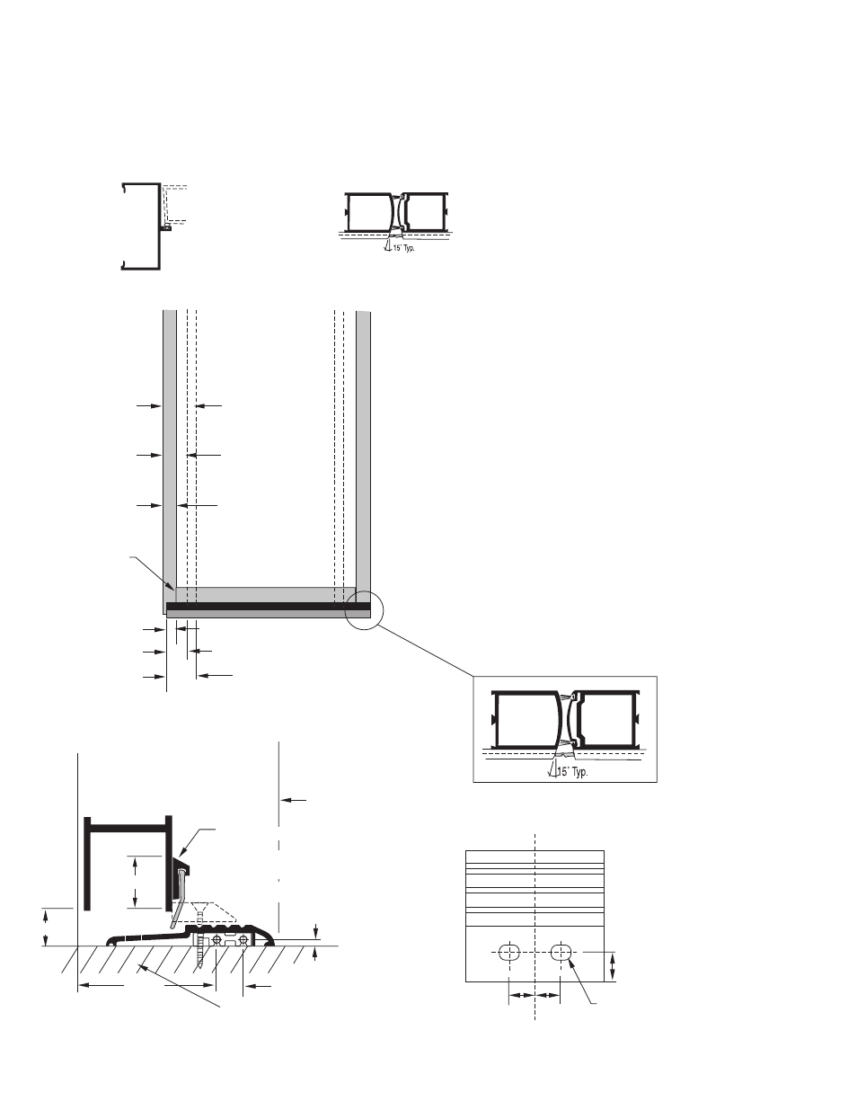
INSTALLATION INSTRUCTIONS FOR HIGH-PERFORMANCE THRESHOLD
PAIR OF DOORS
BUTT HINGE OR
OFFSET PIVOT
1. Determine door type, mark placement as shown
in (fig. 3). Place weather-strip on door and mark
for 15 degrees cut as shown in (fig. 4). Cut
weather strip.
2. Place weather strip on door 1-1/16" up and
mark attachment holes using weather strip as
template. Drill for #8 x 1/2" FHSMS and attach
weather strip.
3. Install silicone strip allowing over lap as shown
in (fig. 4) and crimp pivot end.
4. On both frame jambs drill two #29 (.136" dia.)
holes in frame for #FS-256 screws and attach
clips to frame (fig 5). Drill one #2 (.211" dia.)
hole 1/2" in from each end of the threshold as
shown in (fig. 2) and countersink for #12
FHSMS #FS-42. Attach threshold to clips.
5. For doors with concealed rod panics drill holes
in threshold as shown in (fig. 6). Be sure to drill
into condition below to allow rod to engage into
threshold as shown in (fig. 5). Attach #3315
stop.
6. Seal threshold to frame and surrounding
conditions.
INSIDE
WIDE STILE DOOR
MEDIUM STILE DOOR
NARROW STILE DOOR
1 11/16"
3 5/32"
4 9/16"
11/16"
Ref.
1 1/16"
2 3/4"
5/8"
FG-1118
5/32"
BOTTOM RAIL AND
STILE MEET
DRILL 17/32" Dia. x 11/16"
LONG SLOT
29/32" 29/32"
CENTERLINE OF THRESHOLD
7/8"
TH-49
D-118 ATTACH WITH #8 SCREW
D-120 RAZOR TRIM AROUND
THRESHOLD STOP
D134-2
DRILL INTO CONCRETE TO INSURE
PANIC ROD PENETRATION
MRP# 3315
Figure 3
Figure 4
Figure 6
Figure 5
13
MAY 2012
D O O R & F R A M E
I N S T A L L A T I O N M A N U A L
Web Address: www.oldcastlebe.com
Phone: 1-866-OLDCASTLE (653-2278)