Losb0203mini-baja_manual 7.pdf – Losi LOSB0203 Manual User Manual
Page 7
Page 7
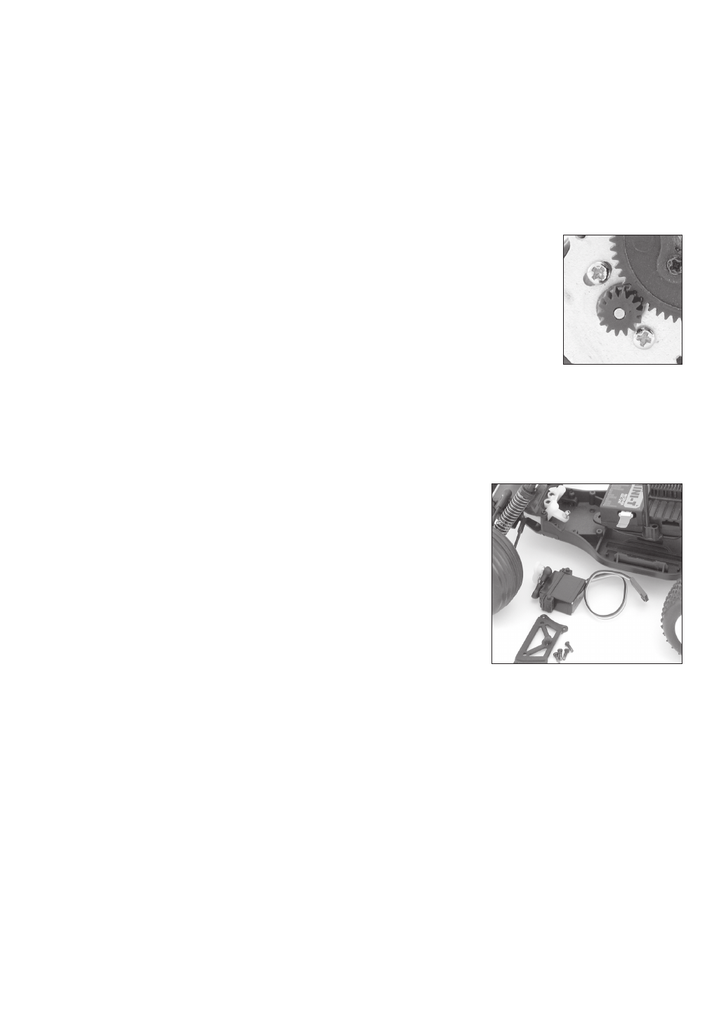
Changing the Pinion Gear/Gear Ratio
Before you change the pinion gear ask yourself why you are doing it. In general, if you change to a larger pinion the
top speed will improve but you will see less acceleration and run time. This would only be advisable for really long
track layouts with few tight turns. Changing to a smaller pinion will give you quicker acceleration and possibly a bit
longer run time but a little less top speed. This would be good for short layouts or when running hotter motors. The
pinion on the Mini-Baja offers the best balance of both. To change the pinion, remove the gear cover, loosen the
motor screws, and slide the motor back. Use a pair of small needle-nose pliers between the motor plate and back of
the pinion to push the pinion off. Place the new pinion on the end of the motor shaft and, using the flat of the pliers or
a similar flat tool, push it on to the same position as the one removed. If you have changed the size of the spur, see
Setting the Gear Mesh below.
Warning: When running after-market motors, check with the motor manufacturer for correct gearing. Never over-gear
the motor as it can cause overheating, damaging it and the speed control.
Setting the Gear Mesh
The motor screws should be slightly loose. Slide the motor forward allowing the pinion gear
to mesh with the spur gear. Snug (not tight) the bottom motor screw and try rocking the spur
back and forth. There is a slight bit of movement before the motor is forced to turn over. If not,
pull the top of the motor back slightly and recheck. If there is too much slop between the gears,
push the top of the motor forward. When set properly the wheels can be spun forward freely
with very little noise. Make sure to tighten both motor screws and replace the gear cover before
running.
Radio Replacement/Service
If you have a radio problem please call (877) 504-02 for customer service. Most likely, unless you have gotten the
components wet, the service technician can help you fix the problem over the phone. If the problem is more severe,
you may be asked to send in the truck and transmitter or the entire radio system, which would include the receiver/
speed control unit and steering servo. In some cases, like a broken servo or a speed control that has failed due to
getting wet, your local dealer can sell you the a replacement component. The following is complete guide to removing
the system.
Steering Servo
Unplug the servo lead from the receiver. Remove the four small screws that
secure the servo mount/chassis brace to the chassis. Use a screwdriver or small
pliers to pop the steering link off of the servo, so it can be removed. There is no
need to remove the servo mounts on either side as all service can be done with
them on. Replace in the reverse sequence used to remove it.
Receiver/Speed Control (ESC)
Unplug the power lead, motor leads and steering servo. Carefully remove the
antenna wire from the antenna tube. Do not attempt to open the receiver or
electronic speed control (ESC) as only a factory technician has the proper tools
and parts to make any repairs necessary. The receiver and ESC are mounted with double-sided foam tape. Use your
thumb and index finger at the bottom of the front corners to pull them from the mount. If this is difficult, ask for help. If
necessary, carefully use a large flat blade screwdriver between the unit and the mount to pry it loose. Make sure you
remove any left over foam or adhesive before remounting with common servo tape or hobby type foam tape.
Service/Tech Help
(877) 504-0233