Troubleshooting guide – Losi LOS03003 XXX-SCB Brushless RTR User Manual
Page 5
EN
9
EN
8
LOSI XXX-SCT / XXX-SCB RTR • INSTRUCTION MANUAL
LOSI XXX-SCT / XXX-SCB RTR • INSTRUCTION MANUAL
SPECIFICATIONS
Type
Sensorless Brushless/Waterproof
Constant/Peak
45A/290A
Resistance
0.0012 Ohm
Function
Forward Only with Brake
Forward/Reverse with Brake
Operation
Proportional forward,
proportional reverse with braking delay
Battery Type/Input Voltage
2-cell Li-Po/Li-Fe, 4- to 7-cell Ni-MH/Ni-Cd
BEC Output
6V/3A
Overload Protection
Thermal
Dimensions (LxWxH)
1.89 x 1.39 x 1.39 in (48 x 35.2 x 35.2mm)
Weight
2.61 oz (74 g) with wires
ESC LED STATUS
• No ESC LEDs will glow when there is no throttle input from the transmitter.
• The red ESC LED glows when there is any throttle input from the transmitter.
AUDIBLE WARNING TONES
• Input voltage The ESC checks the in put voltage when it is powered ON. If a voltage
problem is detected, the ESC continuously sounds 2 beeps with a 1 second pause
(xx-xx-xx). Power OFF the ESC and ensure the connections are secure and that
the battery power is not too low for safe operation.
• Radio connection The ESC checks radio signal input when it is powered ON.
If a problem is detected, the ESC continuously sounds 1 beep with a 2 second pause
(x--x--x). Power OFF the ESC and ensure the radio system is operating correctly.
DYNAMITE TAZER WATERPROOF 45A SENSORLESS BRUSHLESS ESC, 2S RTR
ESC FUNCTIONS AND MODES
The ESC includes programming options so you can adjust the way your vehicle performs.
Refer to the included settings table to adjust the ESC for your driving conditions.
ESC PROGRAMMING PROCEDURE
Programming is accomplished using the SET button on the ON/OFF switch.
1. Connect a fully charged battery to the ESC.
2. Power ON the ESC.
3. Hold the SET button for 1 second until the green LED blinks, then release the SET button
to enter programming mode.
4. Press and release the SET button as needed to get to the desired menu option (the green
LED will blink corresponding to the menu item number).
5. When at the desired menu item, hold the SET button for 3 seconds until the red LED blinks.
6. Press the SET button to move among the settings based on how many times the red LED
blinks (Refer to the table for more information).
7. Save the setting by holding the SET button for 3 seconds.
8. Power OFF the ESC and repeat the instructions above to change other settings.
Tip: If desired, the ESC programming can be returned to default settings
by powering ON the ESC and holding the SET button for 5 seconds.
ESC CALIBRATION PROCEDURE
Ensure proper ESC function by calibrating the ESC to your transmitter inputs.
1. Power OFF the ESC.
2. Ensure your transmitter is powered ON, the throttle is not reversed, the throttle trim is
neutral and the throttle travel range is at 100%.
3. Press the SET button while powering ON the ESC. Release the button as soon as the
green LED starts to flash.
4. Calibrate the throttle points by pressing the SET button once after each step.
- Neutral (1 flash)—leave the throttle at rest, untouched
- Full throttle (2 flashes)—pull the throttle fully back
- Full brake/reverse (3 flashes)—push the throttle fully forward
5. The motor vibrates for 3 seconds after the last step is completed.
DESCRIPTIONS
1. Running Mode
- Forward Only with Brake
Intended for competition use, this mode allows only forward and brake controls.
- Forward/Reverse with Brake
This mode is the basic all-around mode, allowing forward, reverse and brake controls.
To engage reverse while moving forward, apply the brake until the vehicle has come to
a complete stop, release brake, then apply the brake again. While braking or in reverse,
engaging the throttle will result in the vehicle immediately accelerating forward.
2. Drag Brake Force
Adjusts the amount of brake automatically applied when the throttle is returned to the
neutral position. This simulates the engine braking effect of a full-scale vehicle, allowing
improved turn-in and your vehicle’s general response to controls.
3. Low Voltage Cutoff
This function helps to prevent battery over-discharge. The ESC continuously monitors the
battery’s voltage. If the voltage falls below the voltage threshold for 2 seconds, the output
power shuts off and the red LED flashes twice repeatedly.
The cutoff threshold calculation is based on individual Li-Po cell voltage. For Ni-MH batter-
ies, if the voltage battery pack is higher than 9.0V, it will be treated as a 3-cell Li-Po bat-
tery pack; if it is lower than 9.0V, it will be treated as a 2-cell Li-Po battery pack. Example:
for a 8.0V Ni-MH battery pack used with a 2.6V/cell threshold, it will be treated as a
2-cell Li-Po battery pack and the low-voltage cut-off threshold will be 5.2V (2.6x2=5.2).
4. Start Mode (Punch)
Sets the initial throttle punch when the car accelerates. Level 1 gives
a very soft initial acceleration and level 4 gives a stronger initial acceleration.
5. Max Brake Force
Adjusts the maximum braking force. A higher value provides stronger braking,
but can also cause the wheels to lock, resulting in loss of control of the car.
The black-shaded setting is the factory default.
PROGRAMMABLE ITEMS
PROGRAMMABLE VALUE
1
2
3
4
5
6
7
8
1 Running Mode
Forward with
Brake
Forward/Reverse
with Brake
2 Drag Brake Force
0%
5%
10%
15%
20%
25%
30%
40%
3 Low Voltage Cutoff
non-protection
2.6 V/Cell
2.8 V/Cell
3.0 V/Cell
3.2 V/Cell
3.4 V/Cell
4 Start Mode (Punch)
Level 1
Level 2
Level 3
Level 4
5 Max Brake Force
25%
50%
75%
100%
NOTICE: Always disconnect the battery from the ESC when you have finished operating your vehicle. The ESC switch only controls power to the receiver and servos.
The ESC will continue to draw current when connected to the battery, resulting in possible damage to the battery through over-discharge.
9
8
LOSI XXX-SCT / XXX-SCB RTR • INSTRUCTION MANUAL
LOSI XXX-SCT / XXX-SCB RTR • INSTRUCTION MANUAL
TROUBLESHOOTING GUIDE
PROBLEM
POSSIBLE CAUSE
SOLUTION
Vehicle does not operate
Battery not charged or plugged in
Charge battery/plug in
ESC switch not “On”
Turn on ESC switch
Transmitter not “On” or low battery
Turn on/replace batteries
Motor runs but rear wheels
do not rotate
Pinion not meshing with spur gear
Adjust pinion/spur mesh
Pinion spinning on motor shaft
Tighten pinion gear setscrew on motor shaft flat spot
Transmission gears stripped
Replace transmission gears
Drive pin broken
Check and replace drive pin
Steering does not work
Servo plug not in receiver properly
Make sure the steering servo plug is connected to the receiver steering channel, noting proper polarity
Servo gears or motor damaged
Replace or repair servo
Will not turn one direction
Servo gears damaged
Replace or repair servo
Motor does not run
Motor wire solder joint is damaged
Resolder the motor wire with the proper equipment
Motor wire broken
Repair or replace as needed
ESC damaged
Contact Horizon Hobby Product Support
ESC gets hot
Motor over-geared
Use smaller pinion or larger spur gear
Driveline bound up
Check wheels and transmission for binding
Poor run time and/or sluggish
acceleration
Battery pack not fully charged
Recharge battery
Charger not allowing full charge
Try another charger
Driveline bound up
Check wheels, transmission for binding
Poor range and/or glitching
Transmitter batteries low
Check and replace
Vehicle battery low
Recharge battery
Loose plugs or wires
Check all wire connections and plugs
PRECAUTIONS
• Never touch moving parts.
• Never disassemble while the batteries are installed.
• Always let parts cool before touching.
ADJUSTING THE SLIPPER
Turn the 1/4" (3mm) adjustment nut clockwise (to the right) to reduce the slip
or counterclockwise (to the left) to increase the slip.
GEARING
Your vehicle has been equipped with the optimal gearing for the stock platform. It offers an
ideal balance between speed, power and efficiency. Should you decide to customize your
vehicle with optional batteries or motors, it may be necessary for you to change the pinion or
spur gear.
Installing a pinion gear with less teeth or a spur gear with more teeth will provide greater
torque but will reduce top speed. Likewise, a pinion gear with more teeth or a spur gear with
fewer teeth will reduce torque and increase top speed. Care should be taken when installing
larger pinion gears as this can “overgear” the vehicle, resulting in overheating of the motor
and ESC. When testing different gearing options, pay close attention to the temperature of
the motor and speed control to ensure you are operating within the temperature range of the
components. The motor or ESC should never be so hot that it cannot be touched. If tempera-
tures are too hot, a different gearing combination with a lower pinion gear and/or higher spur
gear is suggested.
CHANGING THE PINION GEAR/GEAR RATIO
1. Unscrew the gear cover screws and remove the gear cover.
2. Loosen the motor screws and slide the motor back.
3. Loosen the set screw and remove the installed pinion gear.
4. Place the new pinion on the end of the motor shaft so the set screw is located
over the flat on the shaft.
5. Position it so the teeth line up with the spur gear and secure the pinion by tightening
the set screw.
6. Set the gear mesh.
7. Reinstall the gear cover.
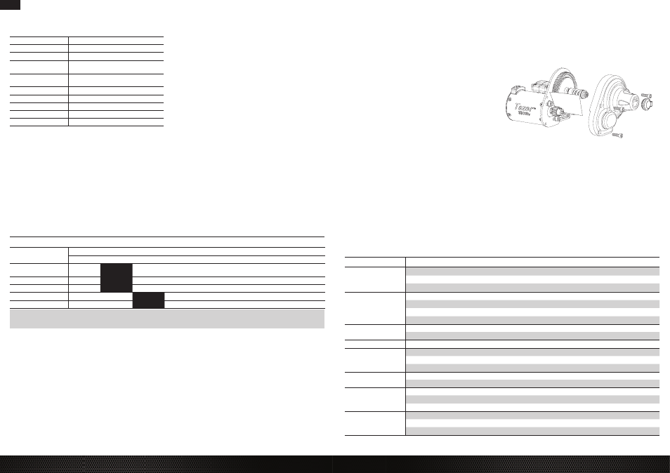
DYNAMITE TAZER 3300KV 4-POLE BRUSHLESS MOTOR (DYN4942)
SETTING THE GEAR MESH
The gear mesh has already been set at the factory. Setting it is only necessary when changing
motors or gears.
Proper gear mesh (how gear teeth meet) is important to the performance of the vehicle. When
the gear mesh is too loose, the spur gear could be damaged by the pinion gear of the motor. If
the mesh is too tight, speed could be limited and the motor and ESC will overheat.
1. Unscrew the gear cover screws and remove the gear cover.
2. Loosen the motor screws and slide the motor back.
3. Put a small piece of paper between the pinion and spur gears.
4. Push the gears together while tightening the motor screws.
5. Remove the paper. Check the mesh at 3–5 different locations around
the spur gear for a small amount of movement.
6. Reinstall the gear cover.