Control cabinet mounting, Refer also to fig. 35 – Kontron KBox C-101 User Manual
Page 41
11. Control Cabinet Mounting
KBox C-101 – User’s Guide (Version 2.00)
11.
Control Cabinet Mounting
Please observe the “General Safety Instructions for IT Equipment” (included) and the installation
instructions (refer to the chapters 4 and 9).
Your KBox C-101 is supplied with assembled mounting plates. The key holes of the upper and lower mounting plates
(Fig. 26, pos. 1 and pos. 3) allow you to mount the KBox C-101 to a mounting side of the control cabinet in vertical
position. This is the only permitted operating position.
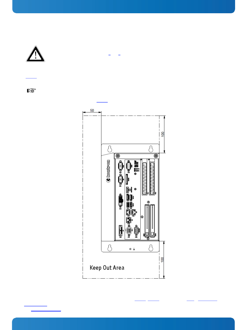
For a sufficient air circulation around the device, we recommend not to place (mount) or operate any
other devices within the “keep out area” marked with “50mm” and “100mm” around the KBox C-101;
refer to the marked area in Fig. 35.
Fig. 35: Keep out area for mounting around KBox C-101 (front side view)
Prepare the mounting surface with four screws and if necessary anchors corresponding to the mounting surface type (fire-
resistant material). Please refer to the information for mounting to Fig. 47, Fig. 48 and the chapter 16.1, “Mechanical
Specifications” or refer to the drawings for KBox C-101 on our web site. The drawings can be downloaded from our web
site
by selecting the product.
www.kontron.com
39