Status and general purpose leds, X205 - optional fieldbus interface, Pcie expansion slots 1 and 2 – Kontron KBox C-101 User Manual
Page 25: Fig. 16: detail - status and general purpose leds, Fig. 17: x205 - optional fieldbus interface, Fig. 18: pcie 1 and pcie 2 slots, Fig. 16) of the drives is green flashing, Green sd led (fig. 16) of
7. System Overview
KBox C-101 – User’s Guide (Version 2.00)
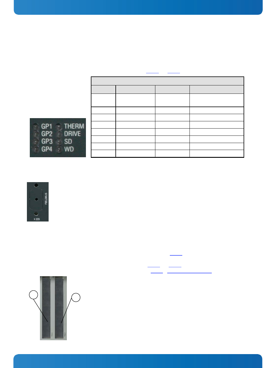
7.3.10. Status and General Purpose LEDs
After power is applied and the KBox C-101 performs the boot procedure the LEDs show the POST code. In case of a boot
failure within the uEFI the last post code is displayed. When the boot phase is passed without errors, the LEDs change to
their status and general purpose function.
The following table provides information concerning these LEDs (Fig. 10 and Fig. 16).
Status and General Purpose LEDs
Designator
Function
Color
Description
THERM Thermal
Red
blinking
The system turns off due to
over temperature
DRIVE
Drives (SSD/HDD)
Green
SSD/HDD active
SD
SD Card
Green
SD card active
WD Watchdog Red
blinking
Watchdog timeout occurred
GP1
General Purpose 1
Red/Green/Orange
User general purpose 1
GP2
General Purpose 2
Red/Green/Orange
User general purpose 2
GP3
General Purpose 3
Red/Green/Orange
User general purpose 3
GP4
General Purpose 4
Red/Green/Orange
User general purpose 4
Fig. 16: Detail - Status and General Purpose LEDs
7.3.11. X205 - Optional FIELDBUS Interface
The optional interface (FIELDBUS) on the front side of the KBox C-101 must
be ordered separately. To add a FIELDBUS interface to the KBox C-101 the
second mPCIe slot, on the bottom of the baseboard, will be used. This
connection can be implemented at factory only.
Fig. 17: X205 - Optional FIELDBUS interface
7.3.12. PCIe Expansion Slots 1 and 2
The KBox C-101 provides two PCIe x4 slots for half-length PCIe add-on cards. The two PCIe x4 expansions utilize a subset
of the connections from the processor chipset PEG port. To access these slots (Fig. 10, PCIe 1 and PCIe 2) in order to
install or remove PCIe x4 expansion cards you have to remove the top side access cover. For better accessibility of the
expansion slots you should to remove the right side access cover (Fig. 24 and Fig. 22, pos 1 and 3) also.
For installation/removing of the mSATA SSD refer to the subsection 10.2.3, “Installing an mSATA SSD”.
1
2
1 PCIe 1 slot
2 PCIe 2 slot
Fig. 18: PCIe 1 and PCIe 2 slots
www.kontron.com
23