Fig. 11: block diagram - kbox c-101, Kbox c-101, Baseboard – Kontron KBox C-101 User Manual
Page 21: Com ex pre ss® - ba sic ty pe 6 module
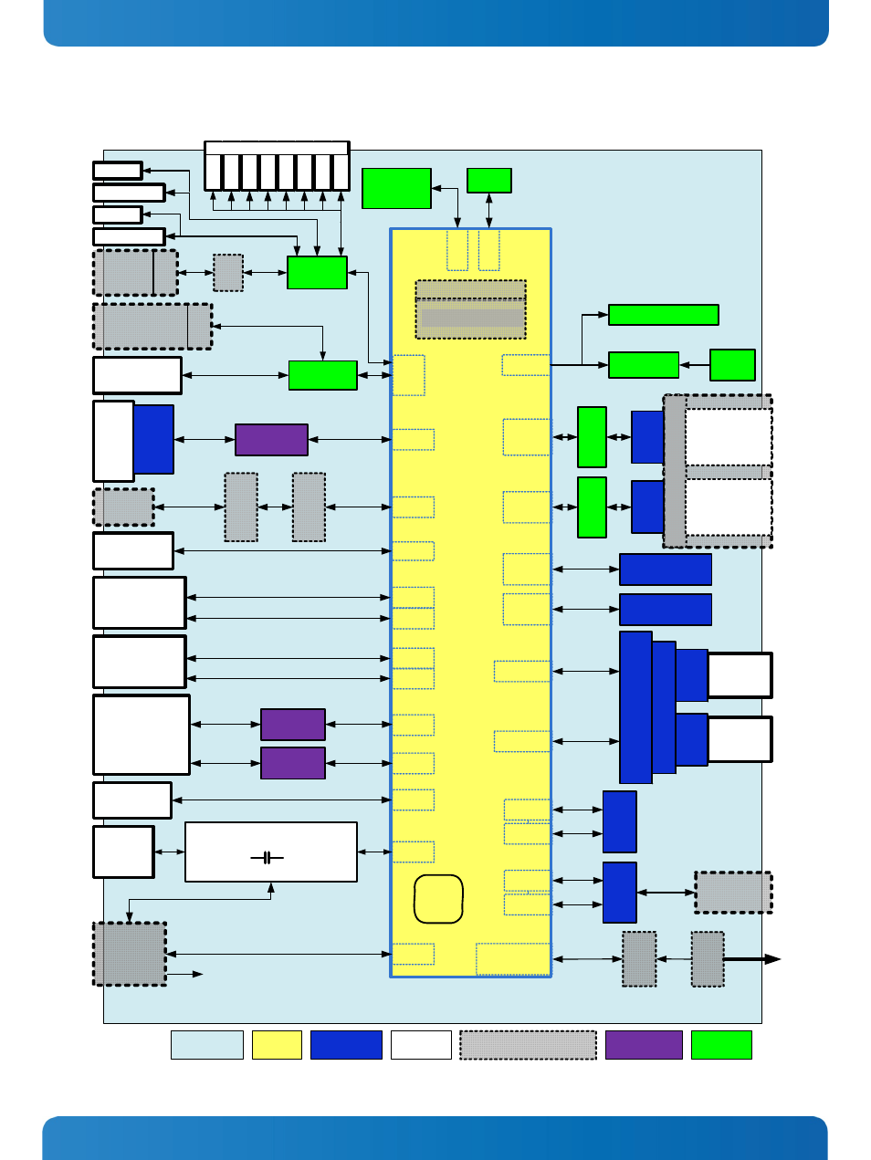
7. System Overview
KBox C-101 – User’s Guide (Version 2.00)
GP
4
GP
3
GP
2
GP
1
WD
SD
DRIV
E
THERM
PWR IN
24 VDC
X 101
Power Supply
and Power Monitor
10 ms Hold-Up
VCC
Gb LAN
Gb LAN
DVI
2x ETH (RJ45)
X 103
X 104
PCIe3
PCIe4
PCIe x1
Gb LAN
Controller
PCIe x1
Gb LAN
Controller
2x USB (2.0)
X 107
X 108
USB6
USB7
Display Port
DVI
LPC
2x USB (3.0)
X 105
X 106
USB1
USB0
ETH (RJ45)
X 102
GBE
LEDs
FAN
Conne
c
tor
FAN_TACHIN
/PWMOUT
Tacho
FAN_CTRL
FA
N
Con
tro
l
to external
Fan Tray
(Option)
UPS
Uninterruptible
Power Supply
X 201
USB8
to CPLD
CPLD
SJ
A
100
0
RS232/RS422
X 204
via Adapter Module
Super I/O
Serial RS232
X 110
SD
Ca
rd
Slo
t
SD
Car
d
Co
nn
ec
to
r
SD Card
Controller
USB2
DVI Port
X 202
DDI2
DP t
o
DVI
Co
nv
er
te
r
DVI
Redr
ive
r
DisplayPort
X 109
DDI1
KBox C-101
PCIe x4
SATA0
6 Gb/s
SATA1
3 Gb/s
SA
T
A
R
e
pe
at
e
r
Inte
rn
a
l o
r
Re
mova
bl
e
Drive 1
for
2.5" HDD/SSD
Drive 2
for
2.5" HDD/SSD
SATA3
6 Gb/s
SATA2
6 Gb/s
mSATA1
Connector (MO-300)
mSATA2
Connector (MO-300)
PEG8-11
PEG12-15
PCIe x4
PCIe 1
Slot
PCIe 2
Slot
Ri
s
e
r Card
PC
Ie
x4
Co
nne
c
to
r
PC
Ie
x
4
Co
nn
ect
o
r
PCIe x1
USB 2.0
PCIe x1
USB 2.0
FIELDBUS
X 205
M
ini
PCIe
Conn
ector
PCIe1
USB4
Mi
ni PCIe
Con
ne
c
tor
PCIe2
USB5
via Adapter
Module
PCIe x
8
Co
nn
ect
o
r
BIOS
Flash
SA
T
A
0
C
onn
ec
tor
SATA1
C
o
nn
ect
o
r
SATA
R
epe
at
er
Baseboard
Legend
COM Ex
pre
ss®
- Ba
sic
Ty
pe
6 Module
Baseboard
COMe
Module
Onboard
connectord
External
interfaces
Optional ext. interfaces and
onboard components
Onboard
controller
Complex
function
RESCUE Button
PWR LED
Power Button
RSQ LED
ga
lva
nic
isol
at
ion
CAN
X 203
gal
va
ni
c
is
olat
io
n
System
EPROM
SPI Flash
RESCUE BIOS
I
2
C
SP
I
Gold
CAP
RTC
Ultra low power
Temperatur Sensor
SMBUS
CPU Options
i5 / i7 / Celeron®
Gb LAN
Fig. 11: Block Diagram - KBox C-101
www.kontron.com
19