2 installing or replacing hard disk drives, Removing an hdd carrier from the chassis – Kontron CG2100 Carrier Grade Server User Manual
Page 41
40
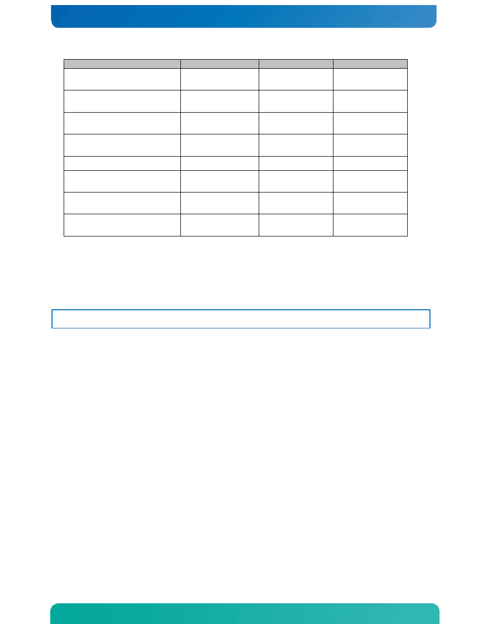
Cable Number and Name
End 1 Connection
End 2 Connection
End 3 Connection
2: Flex Circuit /
Bridgeboard Assembly
SAS/SATA RAID
module
Baseboard
Front panel
board
3: LED/Switch Board
Power and Signal
Front panel
board
LED/switch
board
4: 80mm Fan Power and
Signal
Front panel
board
Ganged cable to
4 fans
5: 60mm Fan Power and
Signal
Front panel
board
Ganged cable to
2 fans
6: Serial Port (COM2)
Bridge board
Baseboard
7: TAM Front Panel
TAM Module
Front Panel
Board
8: USB SD Flash
SD Flash Card
Front Panel
Board
9: Alarms Cable
TAM Module
Chassis Rear
Panel
4.2
Installing or Replacing Hard Disk Drives
Up to six hot-swappable SAS or SATA hard disk drives can be installed in your CG2100
server. The drives go into carriers that connect to the SAS/SATA backplane board once
the carriers with drives attached are inserted back into the drive bays. The CG2100
server ships with six drive carriers.
CAUTION: If you install fewer than six hard disk drives, the unused drive bays must
contain the empty carriers that ship with the server to maintain proper cooling.
The CG2100 server does not support all SAS/SATA hard disk drives. To see a list of
validated manufacturers and drive models, refer to the THOL. The latest version of
the THOL is located on the
(Search for CG2100, click on Product Downloads, then Compatibility Matrix).
You must remove the front bezel to add or replace a hard drive in one of the drive
bays. It is not necessary to remove the front chassis cover or to power down the
system. The hard drives are hot-swappable.
Removing an HDD Carrier from the Chassis
1.
Remove the front bezel. For instructions, see “Removing the Front Cover“ in Section
2.
Select the drive bay where you want to install/replace the drive.
Drive bay 0 must be used first, then drive bay 1 and so on.
(Drive bay numbers are printed on the front panel below the drive bays.)
3.
Remove the drive carrier by pressing the green button to open the lever. (Figure
4.
Pull the drive carrier out of the chassis.
Figure 26. Removing the Drive Carrier