Backplane topology - 11, Om6062r component description – Kontron OM6062 User Manual
Page 33
OM6062R
Component Description
ID: 1031-6374, Rev. 1.0
Page 2 - 11
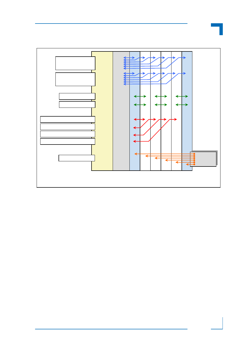
Figure 2-8: Backplane Topology
The topology of the OM6062R backplane permits a wide range of module configurations. There
are, however, some restrictions as to the use of particular module combinations.
If, for example, CPU modules are installed in both slots 1 and 2 (or 3 and 4; or 5 and 6), there
must be no SATA functionality active on AMC ports 2 and 3. If both CPUs have SATA active on
these ports, neither of the CPUs will not properly boot.
When a CPU module which provides PCIe functionality is installed in slot 1 it is the host. There-
fore, any CPU modules installed in slots 2, 3, 4, or 5 must not have PCIe root complex func-
tionality enabled, otherwise the system will not properly boot. It is highly recommended that
Kontron be consulted when considering implementation of systems requiring PCIe functional-
ity.
Common Options
MCH Fabric [A1..6]
to AMC Port 0
Common Options
MCH Fabric [A7..12]
to AMC Port 1
AMC Port 2
AMC Port 3
AMC1 Port 4 to AMC2 Port 4
PCIe CLK
AMC1 Port 5 to AMC3 Port 4
AMC1 Port 6 to AMC4 Port 4
AMC1 Port 7 to AMC5 Port 4
Backplane
PCIe CLK
100 MHz
AMC1
(CPU
)
AMC2
AMC3
AMC4
AMC5
AMC6
(CPU
)
MCH
MCA
Power
Gigabit
Ethernet
SATA
PCIe