Connectors and features, Power supply, Atx connector – Kontron COMe Eval Carrier T10 User Manual
Page 19: 5connectors and features, 1 power supply, 1 atx connector
COM Express® Eval Type 10
/ Connectors and Features
16
5
Connectors and Features
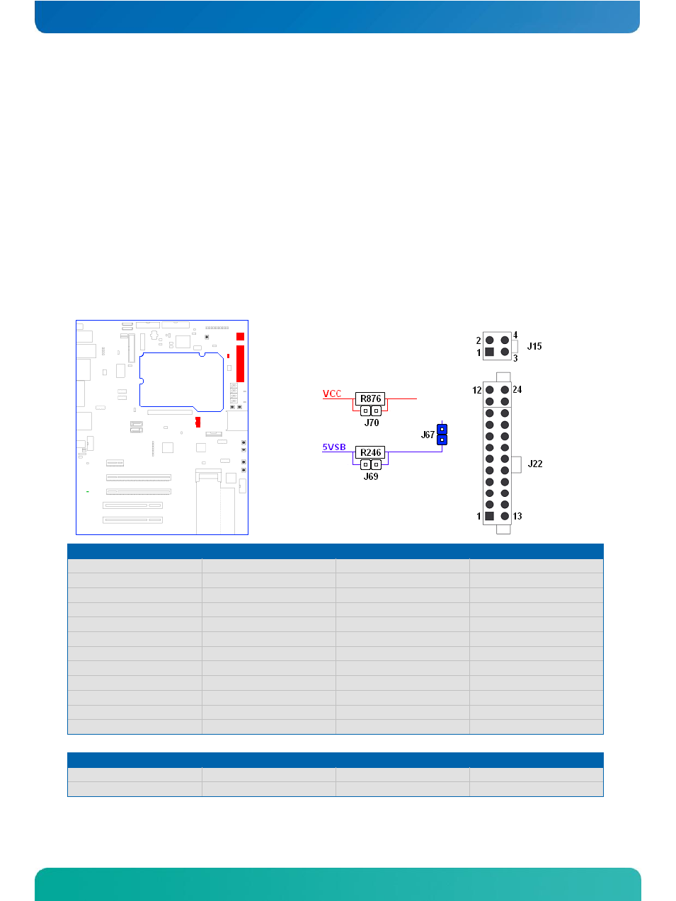
5.1 Power supply
5.1.1 ATX connector
The COM Express® Eval Type 10 power supply follows the ATX 2.x specification and the baseboard should be supplied
by connecting an ATX PSU with 24pin ATX and 4pin ATX_12V supply cable in correct orientation. The 4pin ATX_12V
connector mainly supplies power to the module over 0R resistor R876 and allows powering the module directly in
specified wide range power input. The module additionally is supplied with 5V standby voltage over 0R resistor R246.
Standby voltage can easily be disconnected by opening jumper J67 to drive the module in single supply mode. Use
connector J70 and J69 for current measurements.
Pin
ATX Main Power
Pin
ATX Main Power
1 (Orange)
+3.3V
13 (Orange/Brown)
+3.3V / +3.3V sense
2 (Orange)
+3.3V
14 (Blue)
-12V
3 (Black)
GND
15 (Black)
GND
4 (Red)
+5V
16 (Green)
Power on
5 (Black)
GND
17 (Black)
GND
6 (Red)
+5V
18 (Black)
GND
7 (Black)
GND
19 (Black)
GND
8 (Grey)
PWR_OK
20
No connection
9 (Purple)
+5VSB
21 (Red)
+5V
10 (Yellow)
+12V
22 (Red)
+5V
11 (Yellow)
+12V
23 (Red)
+5V
12 (Orange)
+3.3V
24 (Black)
GND
Pin
ATX_12V
Pin
ATX_12V
1 (Black)
GND
3 (Yellow)
Module VCC (12V nominal)
2 (Black)
GND
4 (Yellow)
Module VCC (12V nominal)