Functional description cp-rio6-001-hd-vga – Kontron CP-RIO6-001-HD-VGA User Manual
Page 36
Functional Description
CP-RIO6-001-HD-VGA
Page 2 - 14
ID 1052-4138, Rev. 1.0
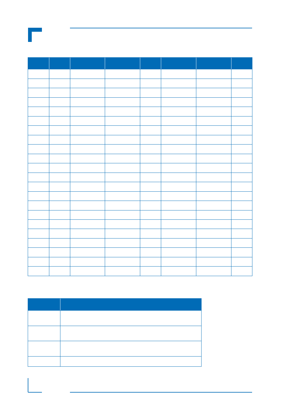
The following table describes the signals of the rJ5 connector.
Table 2-12: Rear I/O CompactPCI Connector rJ5 Pinout
PIN
Z
A
B
C
D
E
F
22
NC
GPIO: *
PWM1:OUT
GND
PWM2:OUT
NC
GND
21
NC
NC
NC
GND
NC
SYS_WP
GND
20
NC
GPIO:0
NC
GND
GPIO:1
NC
GND
19
NC
GND
GND
GND
NC
NC
GND
18
NC
NC
NC
GND
GND
GND
GND
17
NC
NC
NC
GND
NC
NC
GND
16
NC
NC
NC
GND
GPIO: *
GPIO: *
GND
15
NC
NC
NC
GND
NC
NC
GND
14
NC
GND
GND
GND
GND
GND
GND
13
NC
NC
NC
NC
NC
NC
GND
12
NC
NC
NC
NC
NC
NC
GND
11
NC
NC
NC
NC
NC
NC
GND
10
NC
NC
NC
NC
NC
NC
GND
9
NC
GND
GND
GND
GND
GND
GND
8
NC
SATA3:TX+
SATA3:TX-
GND
SATA3:RX+
SATA3:RX-
GND
7
NC
GND
GND
GND
GND
GND
GND
6
NC
RSV
RSV
GND
RSV
RSV
GND
5
NC
GND
GND
GND
GND
GND
GND
4
NC
SATA1:TX+
SATA1:TX-
GND
SATA1:RX+
SATA1:RX-
GND
3
NC
GND
GND
GND
GND
GND
GND
2
NC
RSV
RSV
GND
RSV
RSV
GND
1
NC
GND
GND
GND
GND
GND
GND
Table 2-13: Rear I/O CompactPCI Rear I/O Connector rJ5 Signals
SIGNAL
DESCRIPTION
SATA1 and
SATA3
SATA Port 1 and Port 3 Signaling
GPIO
General Purpose IO Signaling (direction and voltage leveling depends
on CPU board functionality)
GPIO *
General Purpose IO Signaling: on request only (direction and voltage
leveling depends on CPU board functionality)
PWM
Pulse width modulation output for fan