Cp390 introduction, 3 block diagram, 4 board layout – Kontron CP390 User Manual
Page 13
CP390
Introduction
ID 19976, Rev. 0200
Page 1 - 4
® PEP Modular Computers GmbH
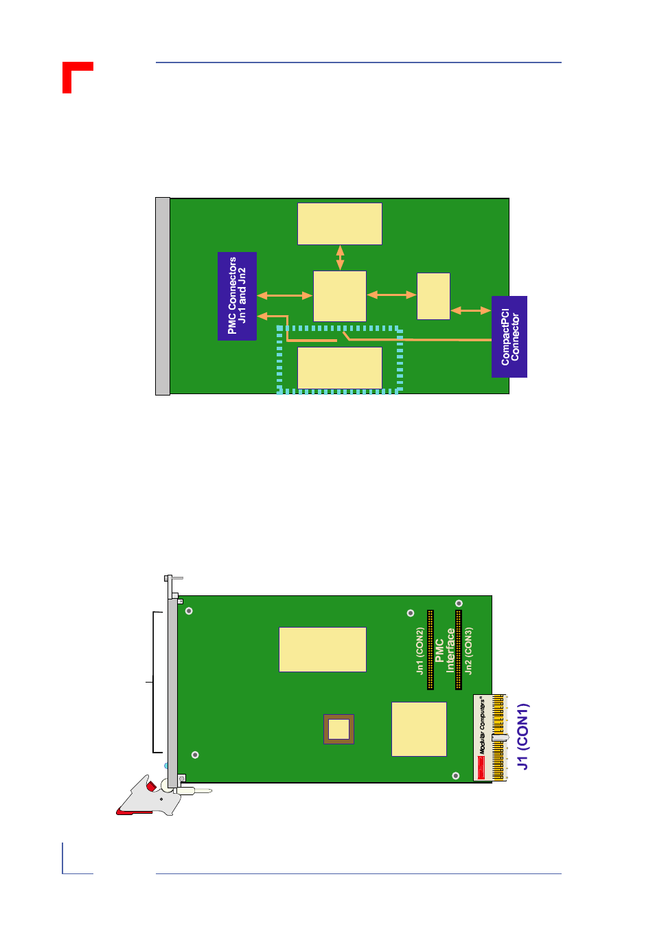
1.3 Block Diagram
Figure 1-1: Block Diagram
1.4 Board Layout
The CP390 has two connectors onboard which provide all the PCI signals and the
power supply for the PMC-Module.
Figure 1-2: Board Layout (Front View)
Serial
Term
Hotswap Control
and
Status Register
Hotswap
Power Control
PCI - PCI
Bridge
Hotswap LED
Power
Controller
Hotswap Control
and Status Register
PCI - PCI
Bridge
Opening for
PMC Module
1
2
63
64
1
2
63
64
See also other documents in the category Kontron Hardware:
- CP3003-SA uEFI BIOS (72 pages)
- CP3003-SA (36 pages)
- CP3002 (38 pages)
- CP3002-RC uEFI (64 pages)
- CP-RIO3-05 (42 pages)
- CP3002-RC (30 pages)
- CP342 (52 pages)
- CP930 (46 pages)
- CP932 (52 pages)
- CP346 (72 pages)
- CP384 (66 pages)
- CP383 (74 pages)
- CP382 (58 pages)
- CP381 (60 pages)
- CP372 (64 pages)
- CP371 (60 pages)
- CP-RIO3-04S (38 pages)
- CPS3410 (9 pages)
- CPS3402 (9 pages)
- CPS3105 (9 pages)
- CPS3101 (9 pages)
- CPS3003-SA (19 pages)
- PB-SIO4 (34 pages)
- PB-SIO4A (34 pages)
- PB-DOUT8 (34 pages)
- VMOD-2 (82 pages)
- VSBC-32 (110 pages)
- VM42 (62 pages)
- Bootstrap Loader (24 pages)
- VMP1 with Netbootloader (120 pages)
- VMP1 (106 pages)
- NetBootLoader (86 pages)
- VMP2 (142 pages)
- VMP3 (154 pages)
- CP-RIO6-923 (32 pages)
- CP-RIO6-923-F (32 pages)
- CP-RIO6-001 (28 pages)
- CP-RIO6-001-HD-VGA (46 pages)
- CP-RIO6-M (20 pages)
- CP-RIO6-B (28 pages)
- CP6925 (42 pages)
- CP6002 uEFI BIOS (76 pages)
- CP6002 IPMI (40 pages)
- CP6002 (42 pages)