4 peripheral control interface, Peripheral control interface - 7, Cp-rio3-04s functional description – Kontron CP-RIO3-04S User Manual
Page 27
CP-RIO3-04S
Functional Description
ID 1036-1669, Rev. 1.0
Page 2 - 7
2.1.4
Peripheral Control Interface
A fan for system cooling and a power supply with power management can be connected to the
CP-RIO3-04S via the peripheral control connector J13.
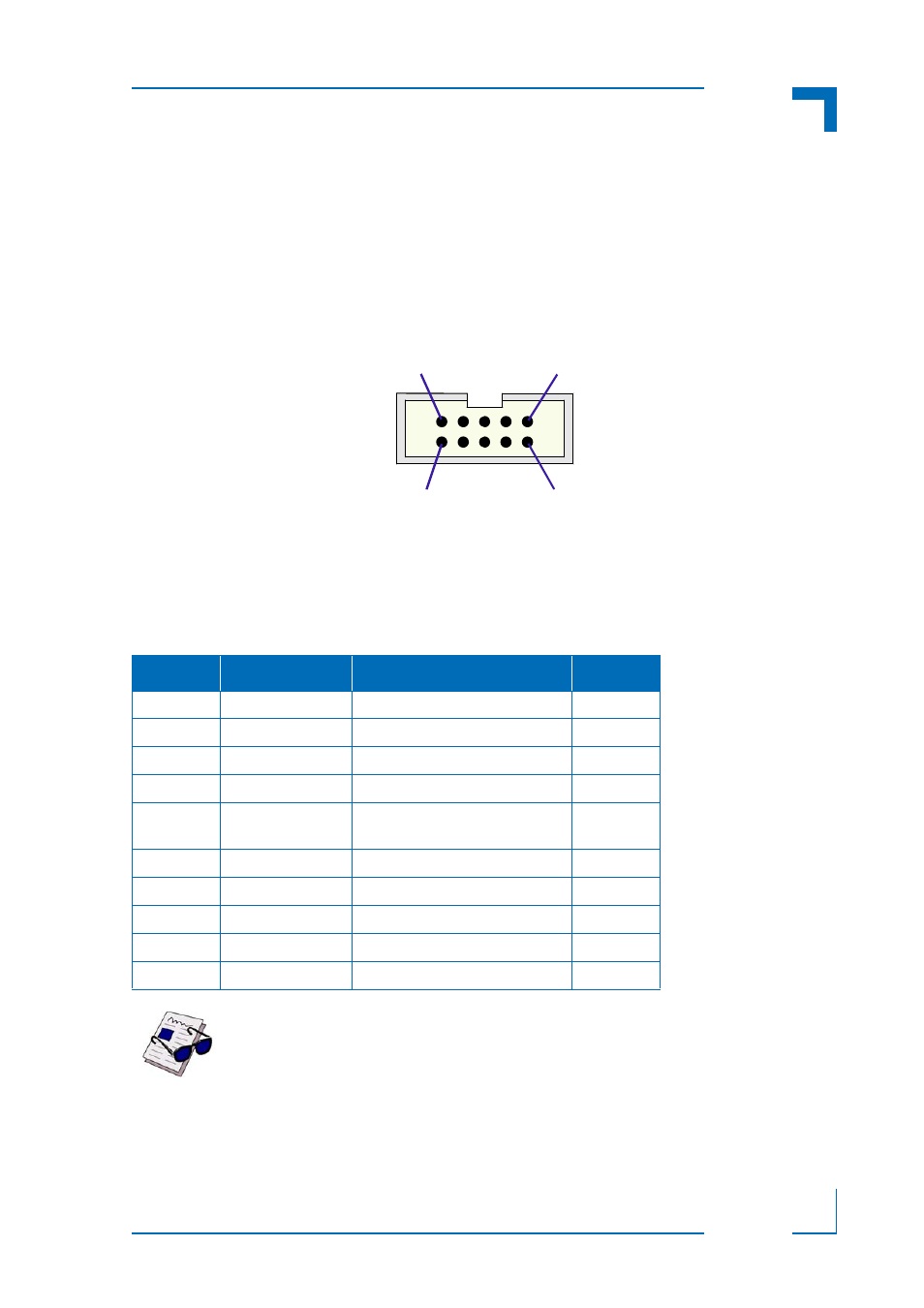
The following figure illustrates the peripheral control connector J13.
Figure 2-5: Peripheral Control Connector J13
The following table indicates the pinout of the peripheral control connector J13.
Table 2-5: Peripheral Connector J13 Pinout
PIN
SIGNAL
DESCRIPTION
I/O
1
GND
Signal ground
--
2
PWR_5VSTDBY
+5V standby power (optional)
I
3
FAN_SENSE
Fan speed monitor
I
4
VCC5V
Power +5V
O
5
PWM_OUT
Fan speed control via pulse with
modulation signal
O
6
VCC3V3
Power +3.3V
O
7
PWR_SLPS3#
Power supply sleep mode
O
8
GND
Signal ground
--
9
PWR_BTN#
Wake-up / sleep input
I
10
GND
Signal ground
--
Note ...
Pin 5 is an open drain output and has no pull-up resistor on the CP-RIO3-04S.
Therefore, an external pull-up resistor is required for fan control operations.
1
9
10
2