3 analog current output signals, Analog current output signals - 4, Cp372 – Kontron CP372 User Manual
Page 50: Con 2, Configuration cp372, Example for cluster a
Configuration
CP372
Page 4 - 4
© 2002 Kontron Modular Computers GmbH
ID 25780, Rev. 01
25780
.01.VC.021
121/1
11237
P R E L I M I N A R Y
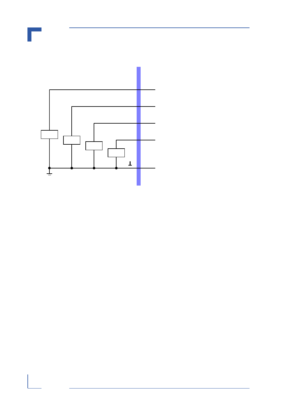
Figure 4-1: Analog Voltage Signal Output Configuration
4.2.3
Analog Current Output Signals
The analog current output signals are single-ended with a range of 0 to 20 mA. Signals of this
type are required to be connected: R
s
to
I
and analog ground to
. Refer to Figure 4-2 for this
type of connection.
As can be seen from Figure 4-2, V
ext
is a function of the source resistance for each individual
output channel of the CP372. To determine the minimum V
ext
required for each channel, use
the following formula:
V
ext
=
I
out
* ( R
ds on
+ R
bias
+ R
s
)
where:
V
ext
=
required minimum external supply voltage
I
out
=
0.02 A
R
dson
=
40 ohms (drain - source resistance)
R
bias
=
250 ohms bias resistance
R
s
=
Example:
I
out
= 0.02 A; R
s
= 1 k ohms
V
ext
=
0.02A * (40 + 250 + 1000)
Ω
= 25.8V (minimum external supply voltage)
R
load
R
load
R
load
+
+
+
+
analog ground
R
load
Example for Cluster A
CON 2
CP372
pin 20 (VOUT0)
pins 38 to 41 (AGND)
pin 19 (VOUT1)
pin 18 (VOUT2)
pin 17 (VOUT3)
T