4 system relevant information, 1 system configuration, 2 driver software – Kontron CP372 User Manual
Page 22: 5 board diagrams, System relevant information - 6, System configuration - 6, Driver software - 6, Board diagrams - 6, Introduction cp372
Introduction
CP372
Page 1 - 6
© 2002 Kontron Modular Computers GmbH
ID 25780, Rev. 01
25780
.01.VC.021
121/1
11236
P R E L I M I N A R Y
1.4
System Relevant Information
The following system relevant information is general in nature but should still be considered
when developing applications using the CP372.
1.4.1
System Configuration
When implementing applications, precautions must be taken to ensure that the output signals
of the CP372 are properly terminated in accordance with the specifications set forth in this man-
ual. For this reason it will be necessary system integrators to ensure proper signal conditioning
for their applications before accepting analog outputs from the CP372. In addition, it is imper-
ative that signal interference be kept to a minimum. Refer to chapters 4 and 5 for further infor-
mation.
1.4.2
Driver Software
The CP372 is supplied with appropriate driver software which provides software interfacing to
the system master.
1.5
Board Diagrams
The following diagrams provide additional information concerning board functionality and com-
ponent layout.
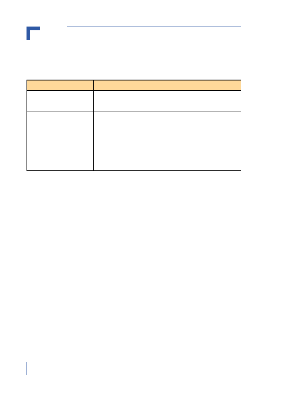
Table 1-2: System Relevant Information
SUBJECT
INFORMATION
System Configuration
The CP372 operates with a system clock frequency of 33 MHz.
The number of CP372’s which can be installed in any one system depends
solely on the number of CPCI slots available.
Master/Slave Functionality
The CP372 functions only as a slave. As such it requires a system master for
servicing.
System Controller
The CP372 cannot function as a system controller.
Analog Outputs
The process interfacing to the CP372 must comply with the output
specifications set forth in this manual.
In particular, for analog current outputs, an external power source is required
to supply an input voltage for generation of the analog output current.
Because this type of output is a direct function of the application, this input
voltage can only be provided by the application.