2 compactpci interface, Compactpci interface - 8, Compactpci connector j1 pinout - 8 – Kontron CP932 User Manual
Page 34: Compactpci connector j1 - 8, Functional description cp932
Functional Description
CP932
Page 2 - 8
© 2005 Kontron Modular Computers GmbH
ID 30048, Rev. 01
3004
8.01.UG.VC.050622/19130
1
P R E L I M I N A R Y
2.5.2
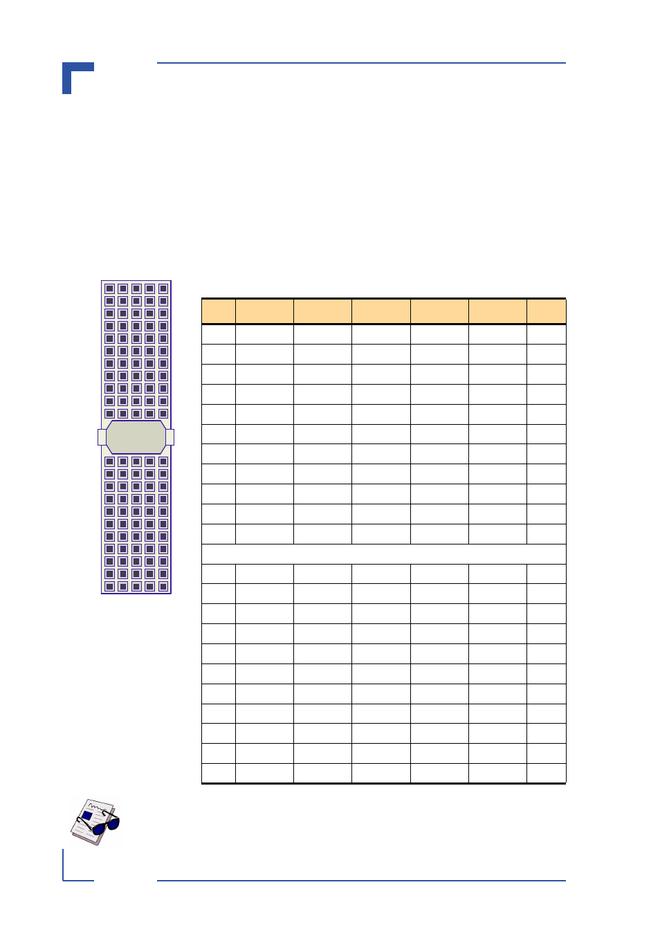
CompactPCI Interface
The CP932 is equipped with one 2 mm x 2 mm pitch, 32-bit, female, CompactPCI connector,
J1, with support for PCI bus signals, arbitration, clock and power.
The CP932 is designed for a CompactPCI bus architecture. The CompactPCI standard is elec-
trically identical to the PCI local bus. However, these systems are enhanced to operate in rug-
ged industrial environments and to support multiple slots.
The CompactPCI interface is based on the specification PICMG 2.0 R 3.0, 10/1/99. The follow-
ing figure and table indicate the pin layout and pinout of the CompactPCI connector, J1.
Figure 2-3: CompactPCI Connector J1
Table 2-2: CompactPCI Connector J1 Pinout
PIN
ROW A
ROW B
ROW C
ROW D
ROW E ROW F
25
+5V
NC
NC
NC
+5V
GND
24
AD[1]
+5V
V(I/O)
AD[0]
NC
GND
23
NC
AD[4]
AD[3]
+5V
AD[2]
GND
22
AD[7]
GND
NC
AD[6]
AD[5]
GND
21
NC
AD[9]
AD[8]
M66EN
C/BE[0]#
GND
20
AD[12]
GND
V(I/O)
AD[11]
AD[10]
GND
19
NC
AD[15]
AD[14]
GND
AD[13]
GND
18
SERR#
GND
NC
PAR
C/BE[1]#
GND
17
NC
NC
NC
GND
PERR#
GND
16
DEVSEL#
GND
V(I/O)
STOP#
LOCK#
GND
15
NC
FRAME#
IRDY#
GND
TRDY#
GND
12-14 Key Area
11
AD[18]
AD[17]
AD[16]
GND
C/BE[2]#
GND
10
AD[21]
GND
NC
AD[20]
AD[19]
GND
9
C/BE[3]#
IDSEL
AD[23]
GND
AD[22]
GND
8
AD[26]
GND
V(I/O)
AD[25]
AD[24]
GND
7
AD[30]
AD[29]
AD[28]
GND
AD[27]
GND
6
REQ#
GND
NC
CLK
AD[31]
GND
5
NC
NC
RST#
GND
GNT#
GND
4
NC
NC
V(I/O)
NC
NC
GND
3
INTA#
NC
NC
+5V
NC
GND
2
NC
+5V
NC
TDO
TDI
GND
1
+5V
NC
NC
NC
+5V
GND
Note ...
On the five-channel variant of the CP932, the PCI signals are not connected.
Note:
Pinrow
F
comprises
GND pins.
25
A
E
C
1
D
B
F