Pyromaster, H33bdvrrn/p – Vermont Casting H33BDVRRN User Manual
Page 29
29
Pyromaster
©
H33BDVRRN/P
10004798
The fireplace, when installed, must be
electrically connected and grounded in
accordance with local codes or, in the
absence of local codes, with the current
CSA C22.1 Canadian Electric Code.
For USA installations follow the local
codes and the national electrical code
ANSI/NFPA No. 70.
Should this fan require servicing or
repair the power supply must be
disconnected. For rewiring of any
replacement parts refer to Figure 43.
Any electrical rewiring of this fan must
be done by a licensed electrician.
Wiring Instructions
Black
White
Ground
Fan
Temperature
Sensor
Speed Control
FP1025
Fig. 43 FK24 fan wiring.
The fireplace, when installed, must be
electrically connected and grounded in
accordance with local codes or, in the
absence of local codes, with the current
CSA C22.1 Canadian Electrical Code.
For USA installations follow local codes
and the national electrical code ANSI/
NFPA No. 70.
It is strongly suggested that the wiring
of the EB-1 Electrical Junction Box be
carried out by a licensed electrician.
Ensure that the power to the supply line
has been disconnected before com-
mencing this procedure.
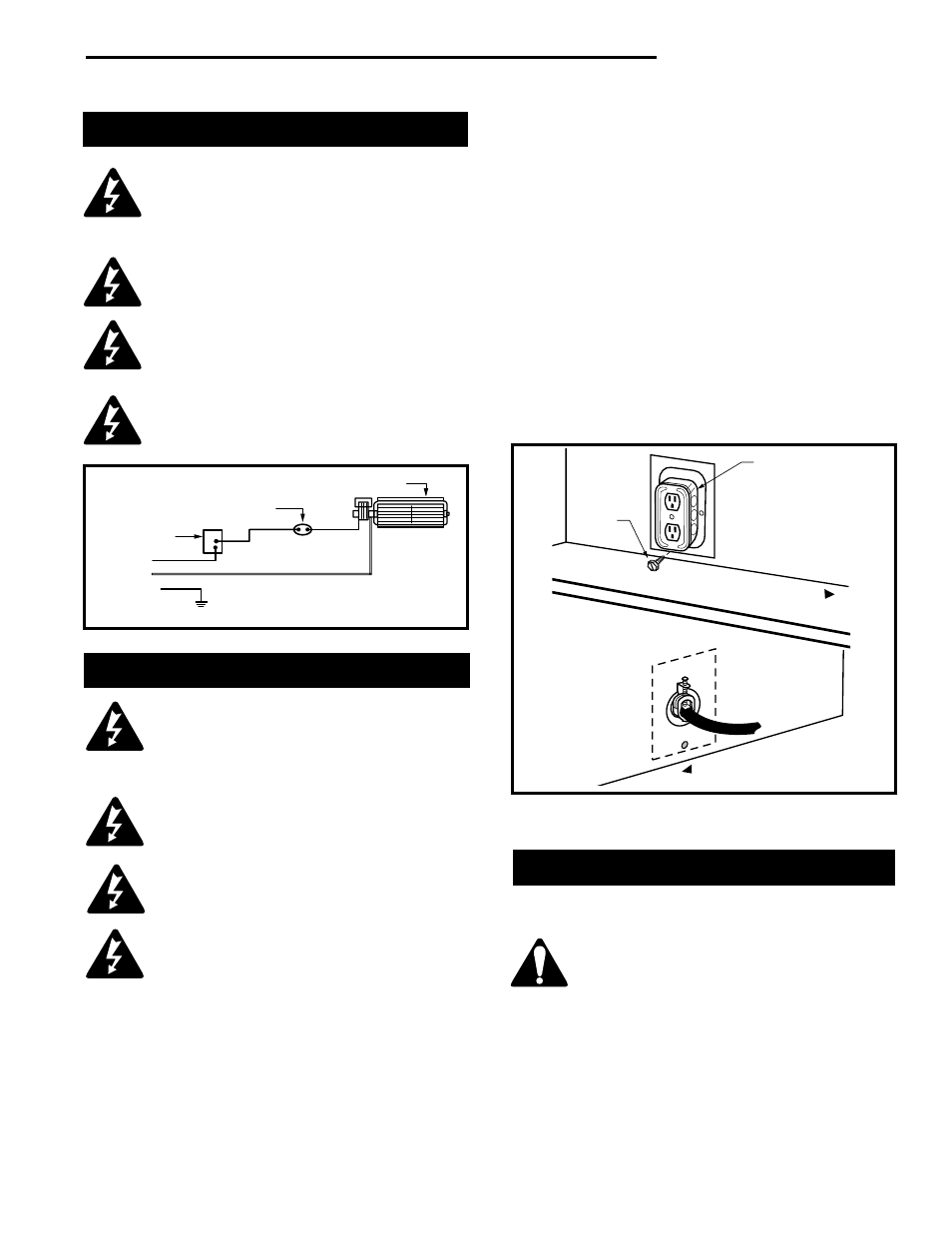
EB-1 Electrical Box
3. Remove the plug socket assembly from the EB-1
box.
4. Feed the supply line in through the EB-1 opening in
the side of the appliance and then through the back
of the EB-1 assembly. (Fig. 44)
5. Connect the black wire of the power supply line to
the brass screw (polarized) of the socket assembly.
6. Connect the white wire of the power line to the
chrome screw of the socket assembly.
7. Connect the ground wire of the supply line to the
green screw of the socket assembly.
8. Refit the socket assembly back into the electrical
box and replace the cover plate. Secure the cable
with the clamp on the outside of the EB-1 base
plate and attach the EB-1 assembly to the unit with
the screw removed in step 1.
The EB-1 Electrical junction box option is available to
allow for the easy connection of an optional fan kit.
To connect the EB-1 box to the house electrical supply
follow the steps below.
1. Unscrew the retaining screw from the plate and
remove from the appliance. (Fig. 44)
2. Remove the front cover of the EB-1 box.
Ceramic Refractory Panel Kit #AT1CBB is available for
this appliance.
Take care when handling the refractory
panels as they are fragile until held in
place and supported.
Installation, refer to Figures 45 & 46.
1. Remove the front window frame assembly.
2. Remove the logs.
3. Place the lower supports for the side refractory
panels on the base of the firebox. Place each
support so that the slotted hole fits over the forward
screw head along the edge of the base.
Ceramic Refractory Kits
CFM191a
Fig. 44 EB-1 receptacle.
Front of Unit
Front of Unit
Inside
Outside
Electrical Box
Retaining
Screw