Connessioni connections – FBT MDS 6240 User Manual
Page 11
I
UK
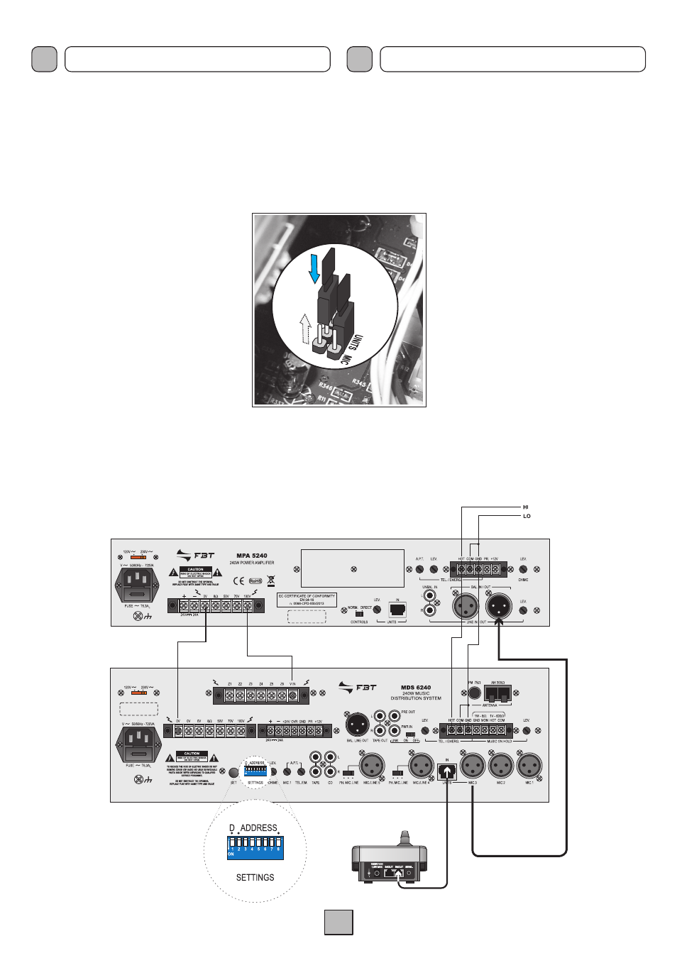
4.10 COLLEGAMENTO AD UN AMpLIFICATORE ESTERNO
Collegando un amplificatore esterno è possibile avere
simultaneamente annunci e musica di sottofondo in zone diverse.
Per sfruttare questa opzione, seguire le indicazioni sottostanti.
CONNESSIONI
CONNECTIONS
1) Rimuovere il coperchio dell’apparecchio
svitando le viti presenti sulle fiancate.
2) Individuare i due jumper evidenziati in
figura 4.10.1 e spostarli dalla posizione
MIC. (impostazione di fabbrica) alla
posizione
UNITS: questo consentirà al
segnale audio proveniente dalle postazioni
microfoniche collegate alla presa
IN
UNITS (22) di venire dirottato in uscita alla
presa
MIC.3.
3) Collegare il morsetto
0V dell’amplificatore
esterno ad uno dei morsetti
0V disponibili
sulla morsettiera (
33) dell’apparecchio.
4) Collegare il morsetto
100V dell’amplificatore
esterno al morsetto
V IN della morsettiera
(
13).
ATTENZIONE! Questa operazione deve essere effettuata SOLO
da personale specializzato: la rimozione del coperchio rende
accessibili parti con rischio di scosse elettriche. prima di rimuovere
il coperchio accertarsi sempre che il cavo di rete sia staccato.
Fig. 4.10.1
5) Collegare tramite cavo bilanciato la presa XLR
MIC.3 (22) con
la spina XLR dell’amplificatore esterno.
6) Abilitare tramite i dip-switches (
16) la modalità di funzionamento
con amplificatore esterno (vedere pag. 11).
Fig. 4.10.2
4.10 CONNECTING TO AN ExTERNAL AMpLIFIER
By connecting an external amplifier, it’s possible to have
announcements and background music simultaneously in different
areas. To exploit this option, follow the directions below.
wARNING! This operation must be performed ONLy by specialists:
the removal of the lid makes accessible parts with risk of electric
shock. Before removing the cover make sure that the network
cable is disconnected.
1) Remove the cover by unscrewing the
screws on the sides of the equipment.
2) Locate the two jumpers illustrated in Figure
4.10.1 and move them out of
MIC position
(factory default) to
UNITS position: this will
allow the audio signal coming from the
microphone stations connected to the
IN
UNITS (22) socket to be diverted to output
socket
MIC.3.
3) Connect the
0V terminal of the amplifier to
an external terminal
0V available on the
terminal strip (
33) of the equipment.
4) Connect the external amplifier
100V
terminal to
V IN of the terminal strip (13).
5) Connect the
MIC.3 socket (22) with a balanced XLR cable with
the XLR plug external amplifier.
6) Enable via the dip-switches (
16) the operation mode with
external amplifier (see page 11).