ETS-Lindgren 2075 MiniMast (Archived) User Manual
Page 14
Electrical Installation
MODEL 2075 MINIMAST™
10
© EMC TEST SYSTEMS, L.P. – MARCH 2002
REV D – PN 399235
branch circuit of adequate current capacity to keep voltage drop to
a minimum during startup and running.
Check that the conductor size is adequate for the motor load and
the distance from the mains source. Improperly sized conductors
will lead to a high voltage drop in the power conductors and cause
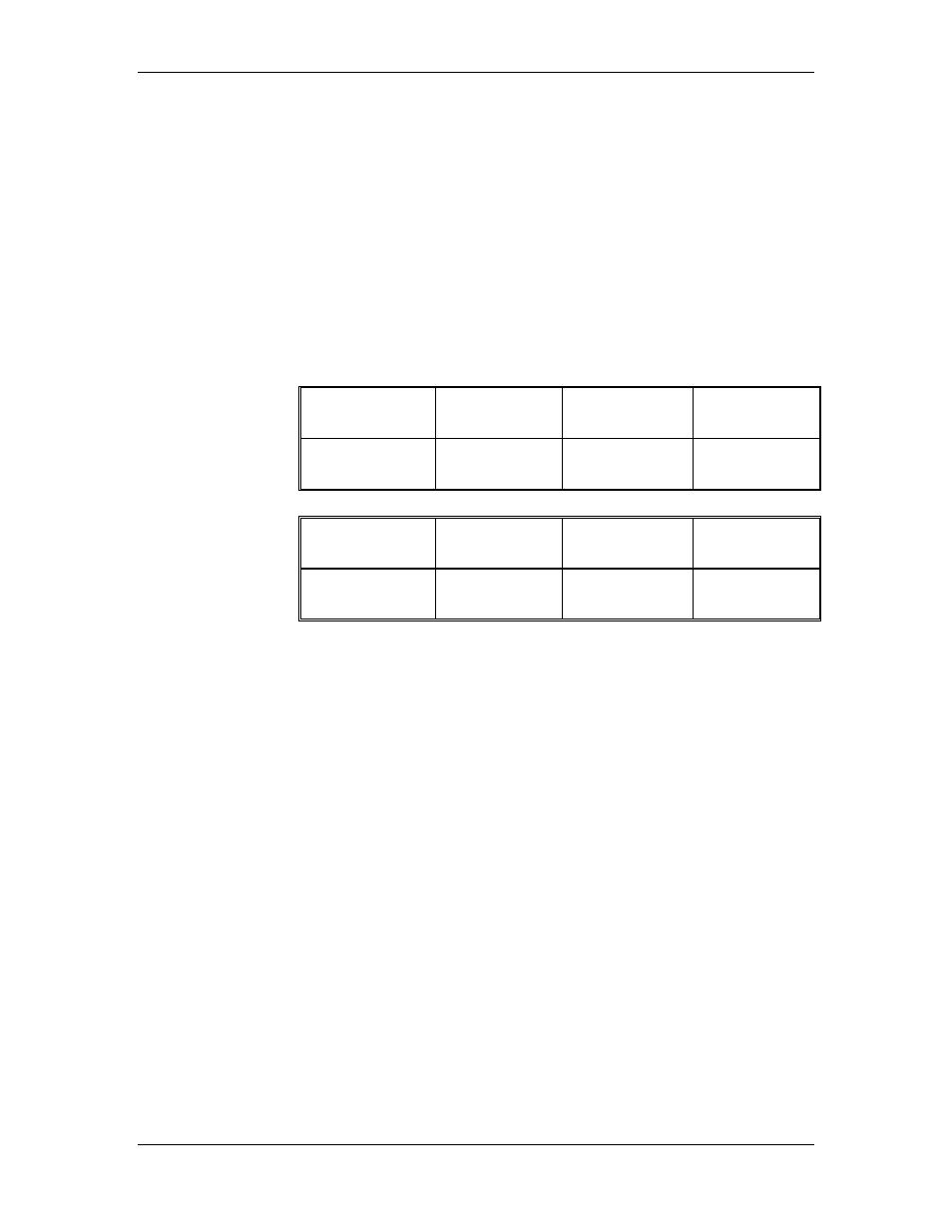
reduced starting torque and premature motor failure. For longer
runs, increase the wire size in accordance with the wire selection
guide shown below. Never use smaller than 14 AWG for any
installation.
Length of wire
@ 115V
0-15.24 m
(0-50 ft)
15.24-30.48m
(50-100 ft)
30.48-60.96 m
(100-200 ft)
Wire gauge
required
14 AWG
10 AWG
8 AWG
Length of wire
@ 220V
0-15.24 m
(0-50 ft)
15.24-30.48m
(50-100 ft)
30.48-60.96 m
(100-200 ft)
Wire gauge
required
14 AWG
14 AWG
14 AWG
If the power cord needs to be replaced, it is recommended that this
alteration be performed at the factory. However, if it is necessary
to modify the electrical cord on site, a qualified, licensed
electrician should perform this operation.
To remove the power input cord:
1. Disconnect the power cord from the supply mains.
2. Remove the clamps that secure the enclosure cover plate in
place and lift the lid.
3. Loosen the plastic strain relief that is around the power cord on
the exterior of the unit.
4. Using a Phillips head screwdriver locate and remove the ten
screws around the edge of the motor base face plate. Gently
remove the face plate and set it down in front of the opening.
IMPORTANT
Do not pull the faceplate away quickly as there
are wires that connect to the faceplate that should remain intact
during this procedure.
Archived 3/18/10