Connection of tubing for reverse osmosis systems – Environmental Water Systems RO4-UV User Manual
Page 11
11
www.ewswater.com O: 702.256.8182; M-F 8:30am-4:30pm PST E: [email protected]
Connection of Tubing for Reverse Osmosis Systems
WARNING:
UPON INSTALLATION SYSTEM MAY HAVE TO BE “BURPED” OF ANY AIR IN THE LINES. UPON COMPLE-
TION OF THE “SYSTEM START-UP AND OPERATION PROCEDURES”. PLEASE REVIEW THIS WARNING
AND DIRECTIONS
Note:
The interconnection between the inlet, outlet, drain and tank lines can cause air in the unit at the control valve.
Air in lines, and at this valve, will not allow system to function properly.
Step 1
This system may have come with sample plugs. If so, please remove correctly by following instructions below before installation.
WARNING:
NEVER ATTEMPT TO REMOVE TUBING OR SAMPLE PLUGS BY JUST PULLING.
Follow simple instructions illustrated below to remove properly.
INSPECT:
Inspect the fitting for any damage from shipping, handling and/or delivery. STOP, if collet is damaged in any way; call, fax or e-mail
customer service for a replacement fitting.
Step 2
For all 3- Stage Systems: Connect the orange/red tubing from the installed Inlet/Supply Connection to the location on the unit
labeled “FEED” to the left of Stage 1. This is the raw supply water into the system. Insert and press the tubing firmly and completely
into the fitting.
For all 4-Stage Systems: Connect the orange/red tubing from the installed Inlet/Supply Connection to the location on the bottom of
the Inline Pre-Sediment Filter prior to Stage 1. This is the raw supply water into the system. Insert and press the tubing firmly and
completely into the fitting.
Step 3
Making the Connections from Faucet/Dispenser to Unit
Connect the blue tubing from the installed Dispenser/Faucet to the location on the unit labeled “FAUCET” to the right of Stage 3
This is the filtered water line. Insert and press the tubing firmly and completely into the fitting.
WARNING:
Install with the “FEED” (in) and “FAUCET” (out) as labeled. Make sure never to reverse directions.
Step 4
Making the Connections from Unit to the Storage Tank
Connect the yellow tubing from the location on the unit labeled “TANK” (If applicable, remove the sample yellow sample plug) to the
installed tank valve on the storage tank. Valve remains closed. Firmly insert the tubing completely into the fitting. You may feel a
resistance at the o-rings when you insert the tubing.
Step 5
Making the Connections from Unit to the Drain Connection(s)
Air Gap:
Connect the black 1/4” tubing from the location on the unit labeled “DRAIN” (If applicable, remove the sample
black sample plug) at the base of the Stage 2 RO membrane cartridge to the 1/4” barb on the air gap adaptor.
Connect the black 3/8”tubing from the 3/8” barb on the air gap adaptor to the 3/8” quick connect fitting installed
on the drain saddle.
Non Air Gap:
Connect the black 1/4” tubing from the location on the unit labeled “DRAIN” (If applicable, remove the sample
black sample plug) at the base of the Stage 2 RO membrane cartridge to the 1/4” quick connect fitting installed
on the drain saddle.
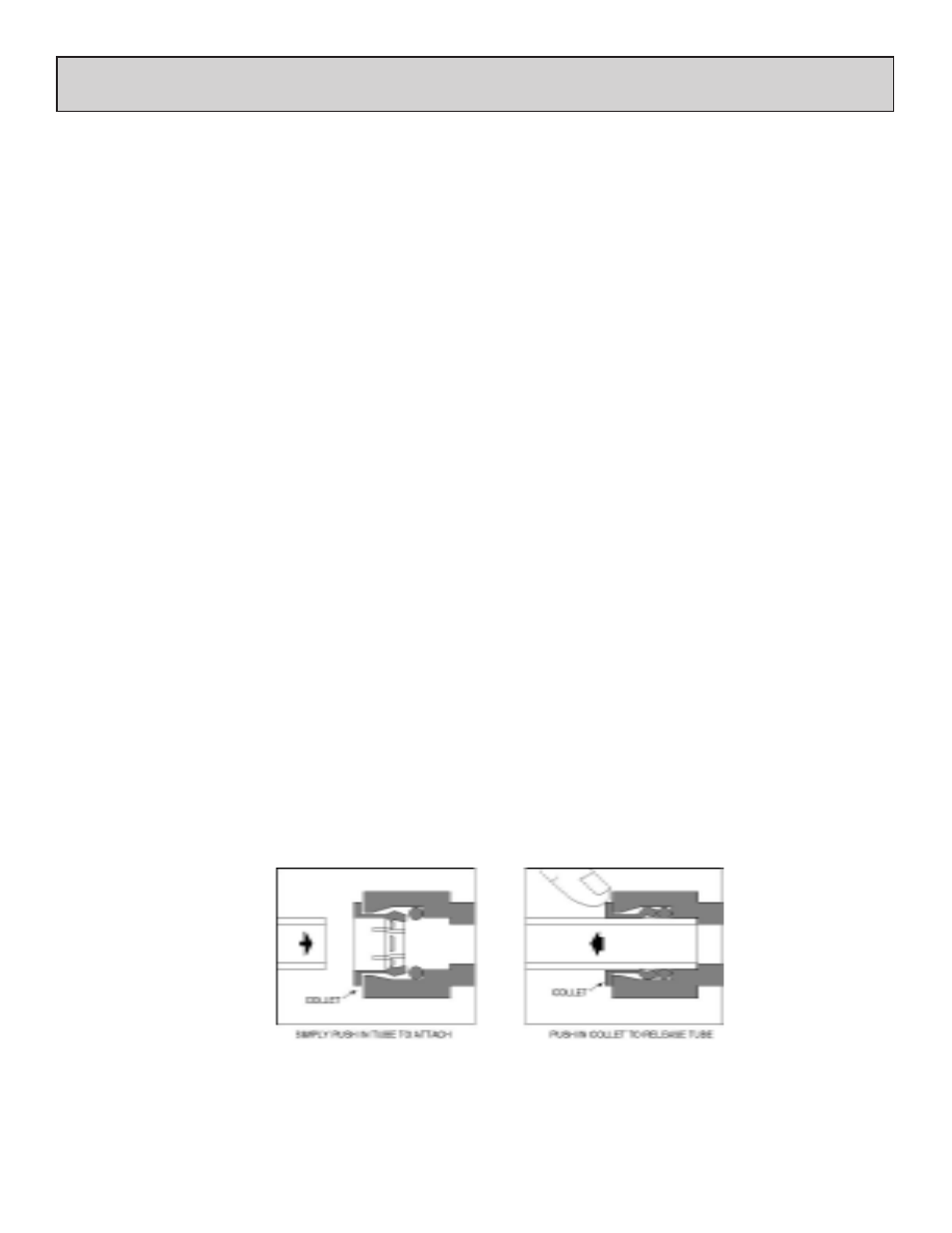
Never Pull Tube Out To Remove
Push Collet In To Release
To Insert, Press Tubing In
Firmly and Completely
Make sure tubing end is straight
and not flattened
Test Integrity of Fitting:
Give a Gentle “Tug” To
Insure Proper Connection
See All Cautions,
Warnings and
Inspections