Series 406x storefront installation instructions – EFCO 406X Series User Manual
Page 7
Series 406X Storefront Installation Instructions
EFCO 2014
Page 7
Section 3A. Screw Spline Fabrication
The screw spline system is a fabrication and erection method that permits the preassembly of single units in the
shop or at the job site. These units are then erected by mating the male mullion of one unit to its counterpart female
mullion of the adjoining unit.
Notes:
1. When an entrance is required, shear block joinery must be used to attach the side lite horizontals.
2. Due to the screw tensions required for correct installation, it will be necessary to ‘wax’ the frame assembly screws to
prevent galling and breaking.
Fabrication Steps:
1. Measure the opening to determine the cut lengths of the frame components.
Allow a minimum 1/4” clearance at head and jambs and 3/4” clearance at the sill for shims and caulking.
Allow extra clearances, if necessary, to accommodate building tolerances and building movement.
2. Cut the vertical to frame size.
Verticals must run through.
If the opening has an entrance, see the appropriate frame and door fabrication installation sheets.
Door jambs run to the floor and are cut longer than other verticals.
3. Drill holes for assembly screws on vertical members per one of the following methods.
Drill jigs are available. (See Page #6)
Layout holes per figures #1,2, or 3 and drill.
Use punch press with appropriate die set.
4. Cut horizontal members to day lite openings. (Between vertical members) Also cut the horizontal glass stops to day
lite opening minus 1/32”. (DLO - 1/32”)
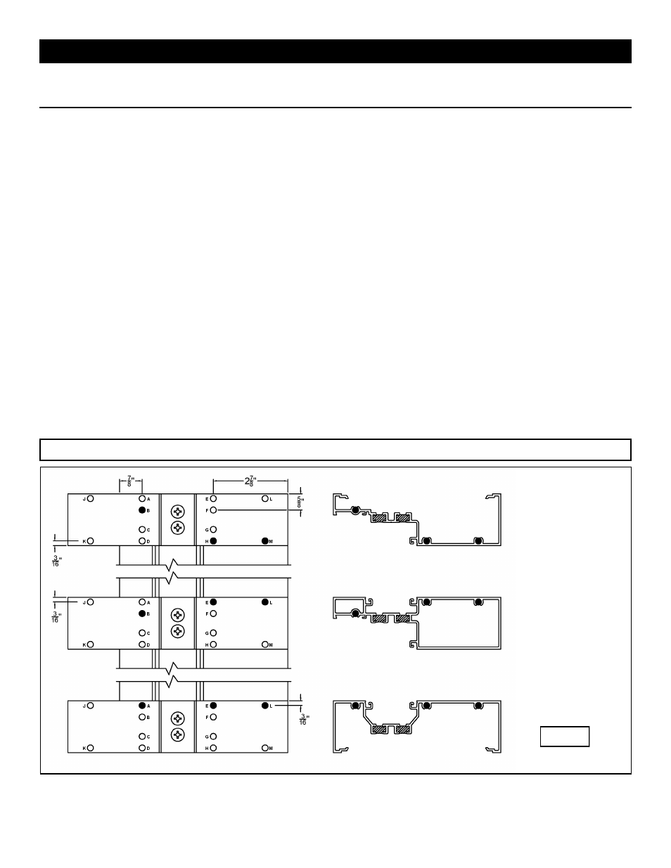
Drilling Templates
Outside Glazed
Bead-Down
Screw Spline
Verticals
Left Hand Shown,
Right Hand
Opposite
Use Drill Jig #DJ51
Use a .230” dia.
No. 1 drill bit at
darkened holes
only.
Fig. #1