Series 403x storefront installation instructions – EFCO 403X Series User Manual
Page 13
Series 403X Storefront Installation Instructions
EFCO 2013
Page 13
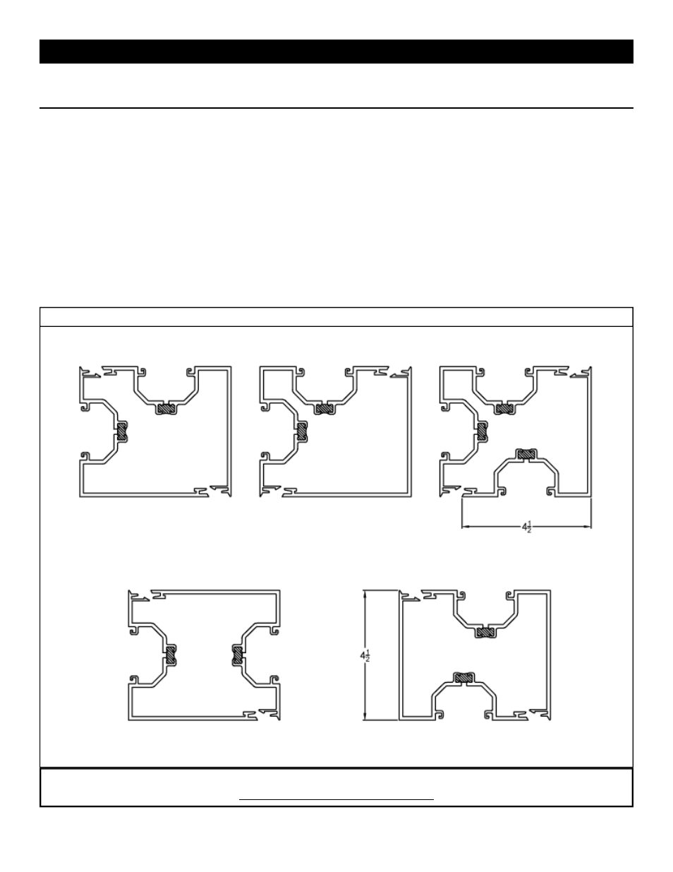
Fig. #10
Notes:
1. 90
⁰ Corners are designed for use with the shear block or screw spline system.
2. Because of possible screw spline and corner snap interference, the 3 way corners must be shear block system only.
3. Do Not measure hole locations from locking corners.
4. All 4 1/2” vertical corners can be mated together or with any other corner regardless of system considerations.
5. The
90
⁰ corner halves may be snapped together and used as a one piece vertical mullion.
6. Refer to current available extrusions for all possible combinations.
Screw Spline System Fabrication Steps:
1. Follow steps 1-3 in Section 3A for cut lengths and hole preparations.
2. Follow standard unit construction method.
Shear Block System Fabrication Steps:
1. Follow steps 1, 2, and 5 in Section 3B for cut lengths and hole preparations.
2. Follow standard unit construction.
Standard Corner Fabrication Combinations
Note:
CORNERS MUST BE SLID APART
*Shear Block Only*
9300
9299 9297
*
Shear Block Only*
8698
9296
9305
8698
9296
9305
8697
9224
9299
9300
9299
8697
9224
9300
8697
9224
9300
Section 3C. Corner Fabrication