EFCO S5500 Inside Glazed User Manual
Page 29
EFCO CORPORATION 6/2012
PART NO. Y552
Series 5500 Inside Glazed Installation Instructions
Section V: Glazing Installation
IMPORTANT NOTE: EFCO recommends using conventional tubular spacers
only for insulated glass units with the S-5500. This is due to the possible
collapse of the spacer when used with drive-in wedge glazing gaskets.
NOTE: Clean all glazing pockets prior to glazing. This is
necessary to avoid clogging the weep system as well as to
prevent staining of the exterior metal and glass surfaces.
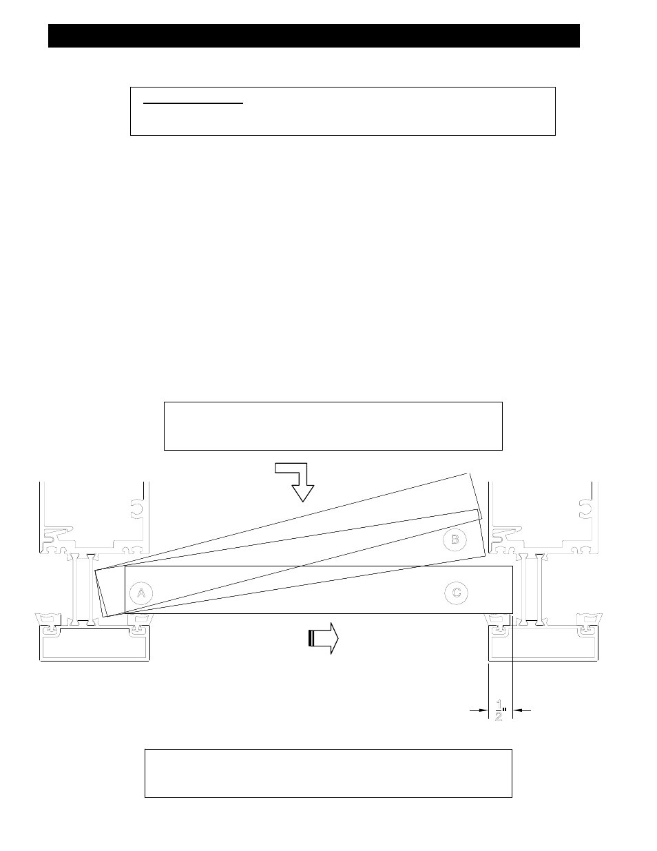
STEP #1 INSTALL GLAZING MATERIALS
A. Using suction cups, gently insert a glass edge (or other glazing infill) into the deep
pocket of the vertical mullion.
B. Swing the opposite edge of the glazing in plane with the shallow pocket of the ad-
jacent vertical mullion, and lower the glazing onto the setting blocks.
C. Position the glazing in the center of the opening maintaining a 1/2” glass bite
around the entire perimeter, except at I.G. heads, where the glass bite is 3/8”.
D. Lift the infill slightly off the setting blocks, and press the glass firmly against the
exterior glazing gaskets at the sill horizontal.
STEP #2 INSTALL TEMPORARY RETAINER GASKETS
A. Use 2” long pieces of the interior wedge gasket to temporarily compress and hold
the glass in the glazing pocket of the verticals. The gaskets should be placed at the
corners of the glazing and then periodically up the vertical. Remove any excess
sealant at the corners of the glazing, on the exterior side, that may ooze out where
the gaskets were butt sealed.
NOTE: The typical glass bite for the I.G. captured system is 1/2”,
except at I.G. heads, where the glass bite is 3/8”. Glass sizes are
based on horizontal D.L.O. plus 1” and vertical D.L.O. plus 7/8”.