Ce door switch, Installing the ce door switch – Dynojet 224: CE Package User Manual
Page 15
I N S T A L L A T I O N G U I D E
CE Door Switch
Version 2
CE Package Installation Guide for 224 Automotive Dynamometers
11
. . . . . . . . . . . . . . . . . . . . . . . . . . . . . . . . . . .
CE DOOR SWITCH
The CE door switch automatically applies the air brake to the dyno when it is
activated. The switch is triggered when the pressure applied to it is released, as when
a door opens.
Components attached to and within the dynamometer operate with potentially
lethal voltages. To provide the greatest assurance of safety, the AC power
cord(s) must be disconnected from the power source before servicing electrical
components or wiring. Disconnect all power cords before servicing electrical
components for the greatest assurance of safety.
I
NSTALLING
THE
CE D
OOR
S
WITCH
1
Turn off the dyno and disconnect the AC power cord from its power source.
2
Remove one of the wires from the brake terminals on the Breakout board that
connect the Breakout board to the brake solenoid.
3
Remove the ferrule attached to the wire.
4
Strip the wire.
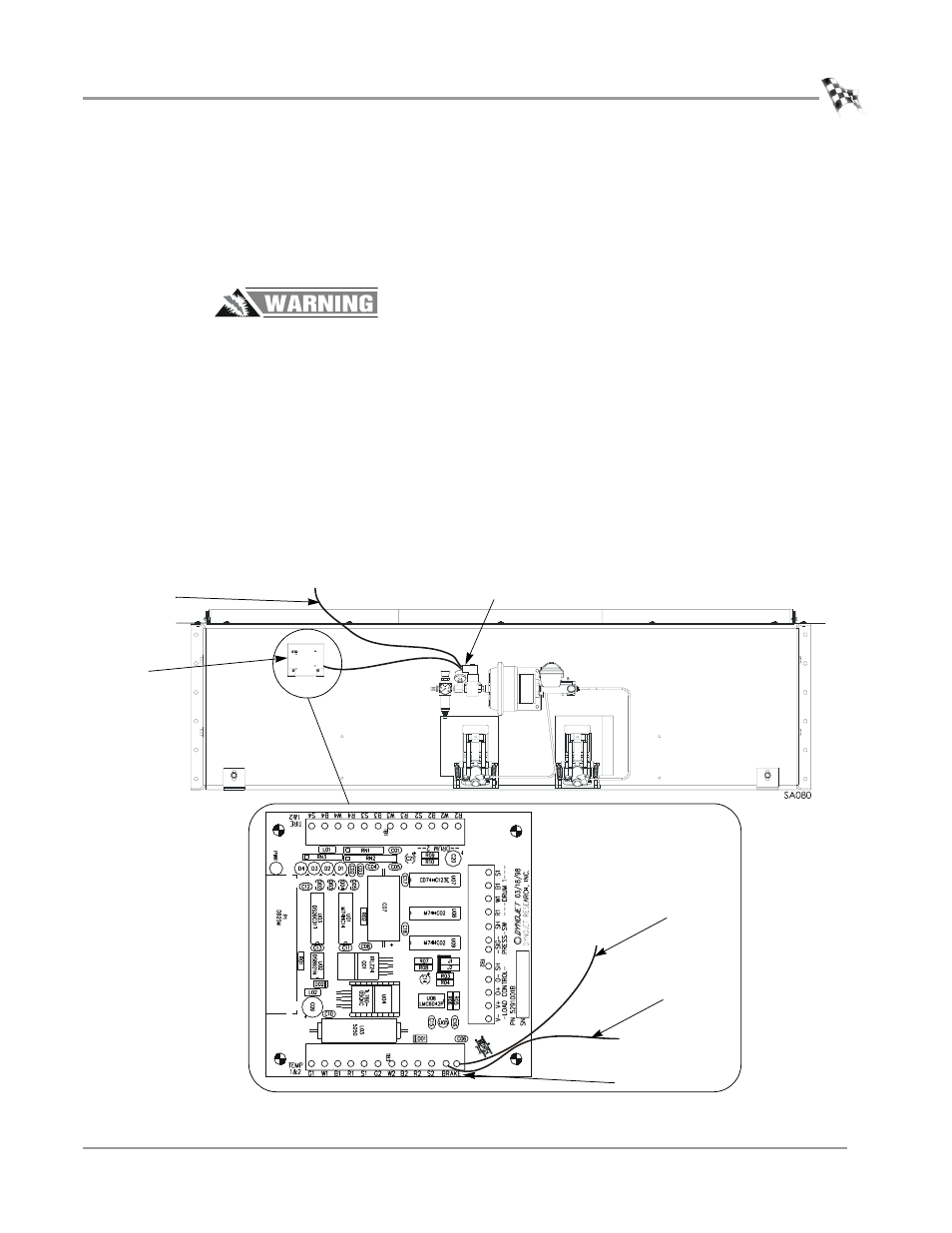
Figure 11: Removing the Brake Wire
stripped
brake wire
Breakout
board
brake solenoid
stripped
brake wire
wire to brake
solenoid
brake terminals