Installation instructions-09 impala-(cont.), Wiring instructions – Code 3 WingMan with TriCore for 2009 Chevy Impala User Manual
Page 4
4
Installation Instructions-09 Impala-(Cont.)
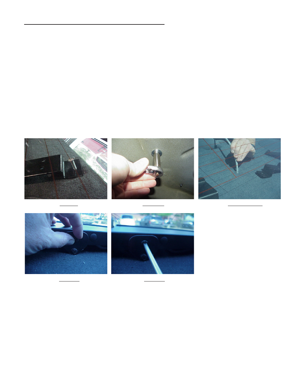
Step 7 Position the Mounting Brackets with the 1/4"-20 X 2 1/2" Hex Head Bolts over the mounting holes in the rear deck and push the
bolts through the holes and through the Mounting Bracket Spacer Bushings as shown in Figure 9. Make sure the Mounting Brackets are
fairly parallel to each other after they are both in place. Thread a fender washer and a 1/4"-20 locking nut onto each of the bolts from inside
the Impala's trunk. Have an assistant using a wrench from the interior of the Impala keep the bolts from turning and tighten the Hex Nuts as
shown in Figure 10.
Step 8 Feed the WingMan™ cable through the cable hole and into the trunk (see Figure 11).
Step 9 Install the WingMan by positioning it over the mounting brackets. You will have to continue feeding the cable through the hole
simultaneously while positioning the bar.
Step 10 As soon as the outer panel mounting plate holes can be lined up with the holes in the mounting brackets
and the mounting holes in the WingMan Bar, insert the (4) supplied 1/4"-20 x 1/2" bolts and internal tooth lock
washers (see Figure 12). Leave the (4) bolts finger tight at this time.
Step 11 Center the light bar in the rear window of the Impala by using a tape measure and adjust the brackets
and mounting plates so that they line up with each other.
Step 12 Tighten the 1/4"-20 X 1/2" bolts with a phillips screwdriver (see Figure 13).
FIGURE 9 FIGURE 10 FIGURE 11
FIGURE 12 FIGURE 13
The bracket fasteners shown in Figures 12 and 13 make excellent hard mounting points for
radar guns, video cameras, etc.
Caution: Drilling into the housing of the light bar could damage wiring or other internal
components.
Wiring Instructions
It is advisable to leave an extra loop of cable when installing the light bar to allow for future changes or reinstallations.
Connect the black lead to a solid frame ground (earth), preferably the (-) or ground (earth) side of the battery, and the
power wire to the +12V terminal of the battery. Connect the remaining wires as shown on page 5.