Wiring instructions, Warning, Product features – Code 3 SuperVisor with TriCore for 2009 Chevy Tahoe User Manual
Page 6: Tri-core, Fusing considerations
6
Wiring Instructions
Larger wires and tight connections will provide longer service life for components. For high current wires it
is highly recommended that terminal blocks or soldered connections be used with shrink tubing to protect
the connections. Do not use insulation displacement connectors (e.g. 3M
®
Scotchlock type connectors).
Route wiring using grommets and sealant when passing through compartment walls. Minimize the number
of splices to reduce voltage drop. High ambient temperatures (e.g. underhood) will significantly reduce the
current carrying capacity of wires, fuses, and circuit breakers. Use "SXL" type wire in engine compartment.
All wiring should conform to the minimum wire size and other recommendations of the manufacturer and
be protected from moving parts and hot surfaces. Looms, grommets, cable ties, and similar installation
hardware should be used to anchor and protect all wiring. Fuses or circuit breakers should be located as
close to the power takeoff points as possible and properly sized to protect the wiring and devices. Particular
attention should be paid to the location and method of making electrical connections and splices to protect
these points from corrosion and loss of conductivity. Ground terminations should only be made to sub-
stantial chassis components, preferably directly to the vehicle battery. The user should install a fuse sized
to approximately 125% of the maximum Amp capacity in the supply line to protect against short circuits.
For example, a 30 Amp fuse should carry a maximum of 24 Amps. DO NOT USE 1/4" DIAMETER GLASS
FUSES AS THEY ARE NOT SUITABLE FOR CONTINUOUS DUTY IN SIZES ABOVE 15 AMPS. Circuit
breakers are very sensitive to high temperatures and will "false trip" when mounted in hot environments or
WARNING!
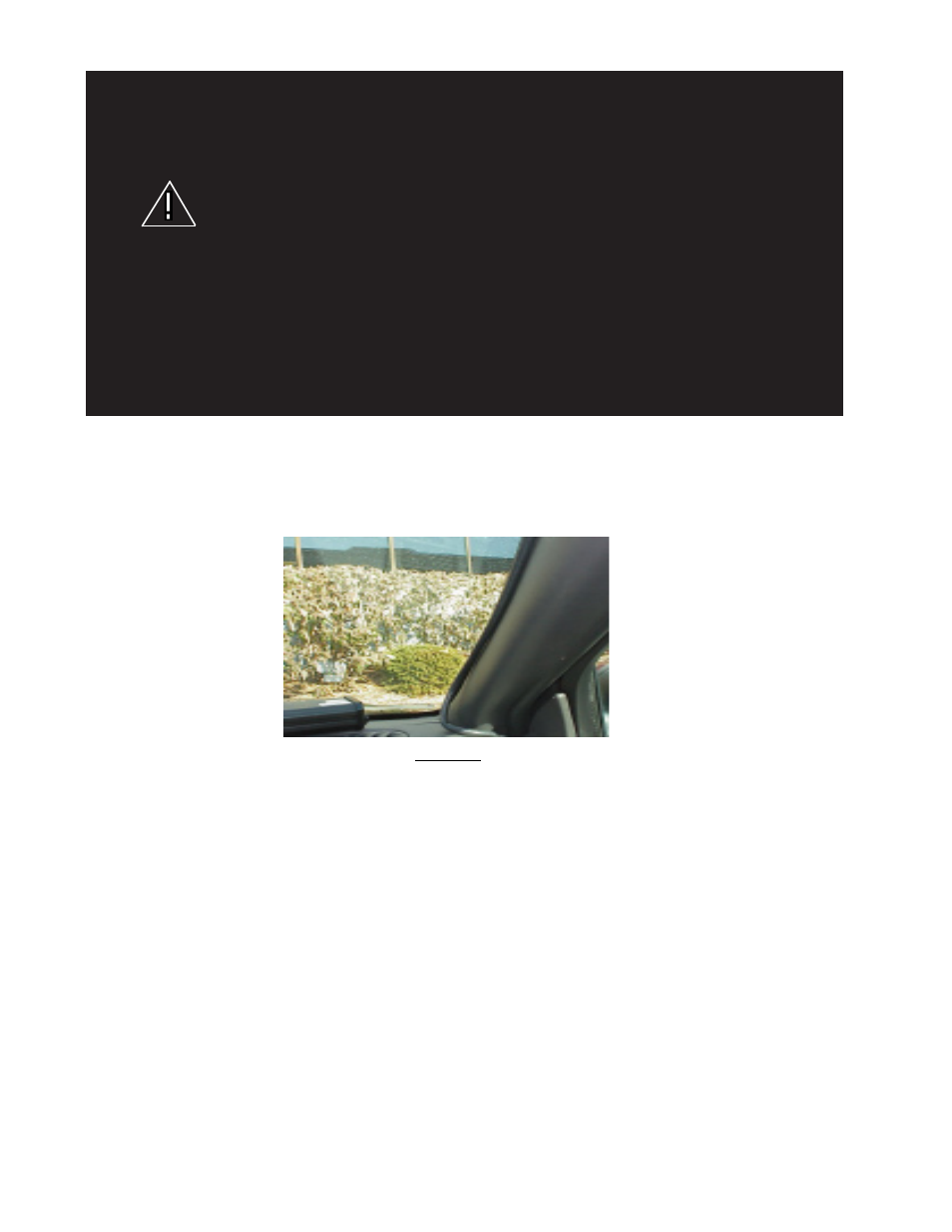
Route the wiring cable into the passenger compartment down the door post as shown in Figure 22 or as otherwise desired.
It is advisable to leave an extra loop of cable when installing the lightbar to allow for future changes or reinstallations. Con-
nect the black lead to a solid frame ground (earth), preferably, the (-) or ground (earth) side of the battery, and the remaining
power wires to the +12V terminal of the battery, power switches, siren or RLS controller. Each lighthead is wired and controlled
through the cnetral controller in the SuperVisor.
FIGURE 22
Product Features
TriCore
TM
lighthead options:
Red, Blue, Amber, White, Green;
Flashing or Steady Burn Control
Size: 50.00" long x 1.54" tall x 5.25" deep
Weight: 7.5 lbs
Tri-Core
TM
Fusing Considerations
Although the average current draw per module is very low, due to the type of circuit used to power each module, the instan-
taneous peak current to a module can be significantly higher during low voltage conditions. To avoid prematurely blowing
ATO style fuses or tripping breakers it is recommended the following rule-of-thumb be used to size fuses or breakers. This is
especially important in lightbars with many Lighthead modules running off a single fused source.
Minimum fuse size calculation:
For Tri-Core
TM
12 volt electrical current only
1.0 X (number of Tri-Core
TM
modules being fused) = Total Electrical Current at 12.8 VDC