Maintenance, Take down and alley flash – Code 3 Solex User Manual
Page 8
Maintenance
Lens Cleaning
Use plain water and a soft cloth, or Code 3® lens polish and a very soft paper towel or facial tissue. Plastic scratches easily, as a result, cleaning is
recommended only when necessary (about every six months). Do not subject the lenses to car washes that use brushes, as these will scratch the
lenses.
Lens Removal
With a Phillips screwdriver, remove the cap attachment screws (with neoprene washers). Insert a small screwdriver blade (or coin) into the small slot
a the corner of the lens cap and twist the screwdriver to lift the cap. Then gently lift the cap off. When finished carefully replace the cap making sure
the lens gasket is not misplaced, then replace the cap mounting screws making sure the neoprene washers are in place.
Light head Removal
Unplug the SIRIS™ light head's power wire/wires from the light bar's wiring harness. Then with a 1/4" Hex Bit Driver, remove the #8 X .270" 6 Lobe
Hex Washer Head Screws that attach the light head mounting bracket to the light bar. The takedowns and alleys require decoupling mated quick-
slide terminals (be sure to pull on the terminals and not the wires).
Take Down and Alley Flash
Selecting Flash Patterns:
The Take Down and Alley Lights can be programmed to flash at different rates.
STEP 1:
Power-up the light bar. Select the Take Down Flash Mode (BLK) or the Alley Flash Mode (BLU/WHT) by applying +power to the appropriate wire. .
NOTE: Make sure +12v is only applied to the function you are trying to program - otherwise program function will
not operate.
STEP 2:
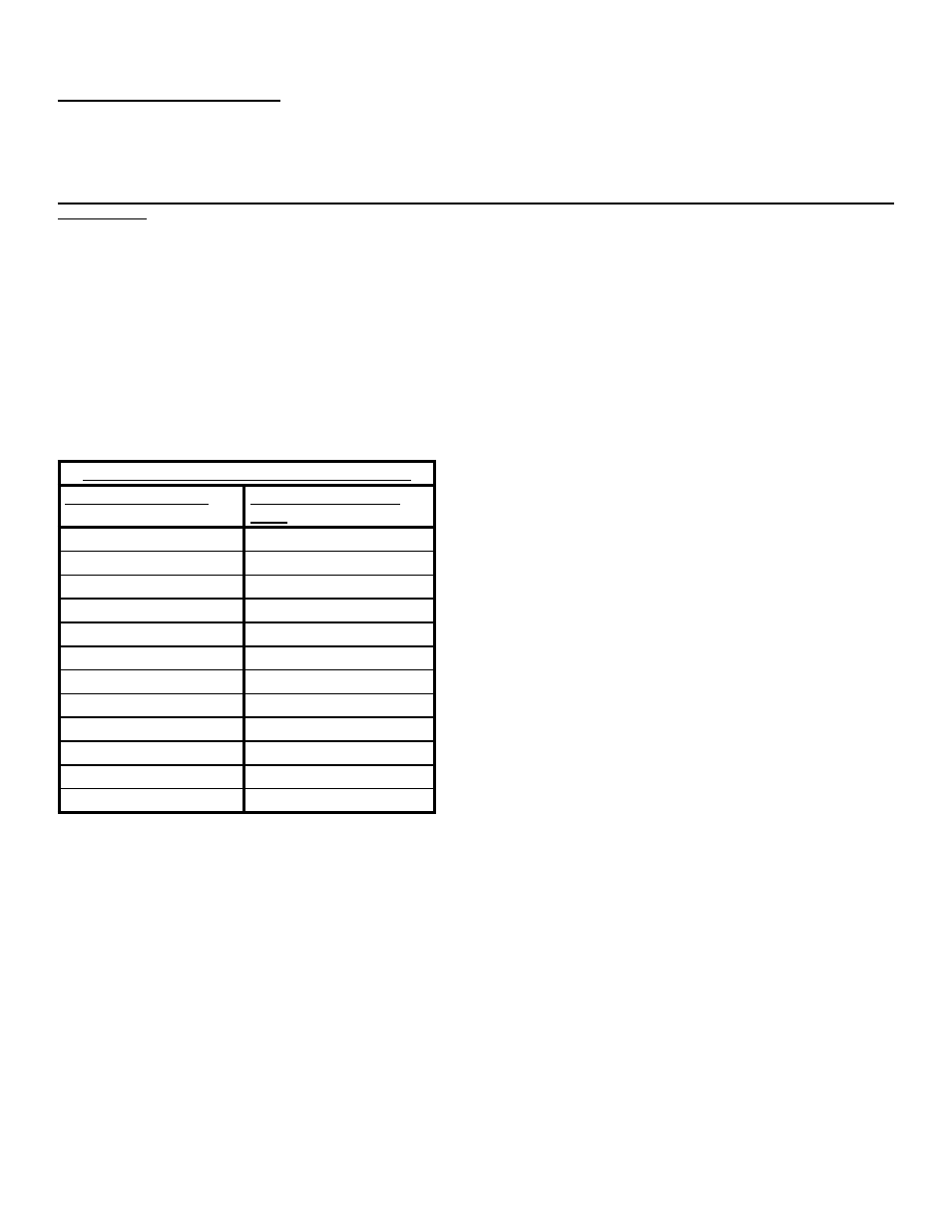
Observe the flash pattern and determine which pattern is in operation (see Table 3). This table shows the available flash patterns. Once the flash
pattern has been determined, proceed to Step 3. NOTE: The default flash pattern for Take Down and Alley Lights is Medium
Single 115FPM.
STEP 3:
Scroll to the next pattern by momentarily holding the BLK/RED wire to +power for ~one (1) second. The light bar will stop flashing when the wire
is connected to +power. Release the wire and the next pattern as listed in Table 3 will begin to flash. The new pattern is automatically stored each
time. NOTE: To restore the Factory Default Take Down and Alley Flash Patterns, hold the bLK/RED wire to +power
for ~four (4) seconds.
TAKE DOwN AND ALLEY FLASh PATTERNS
PATTERN NUMbER
PATTERN DESCRIP-
TION
1
FAST QUAD 80FPM
2
SLOW QUAD 60FPM
3
FAST SINGLE 375FPM
4
MEDIUM SINGLE 115FPM
5
SLOW SINGLE 60FPM
6
FAST DOUBLE 115FPM
7
SLOW DOUBLE 60FPM
8
FAST SIX 80FPM
9
SLOW SIX 60FPM
10
VARIABLE RATE SINGLE
11
NFPA QUAD 75FPM
12
CYCLE FLASH
Table 3