Code 3 PSE690 Remote Strobe Power Supply User Manual
Page 6
6
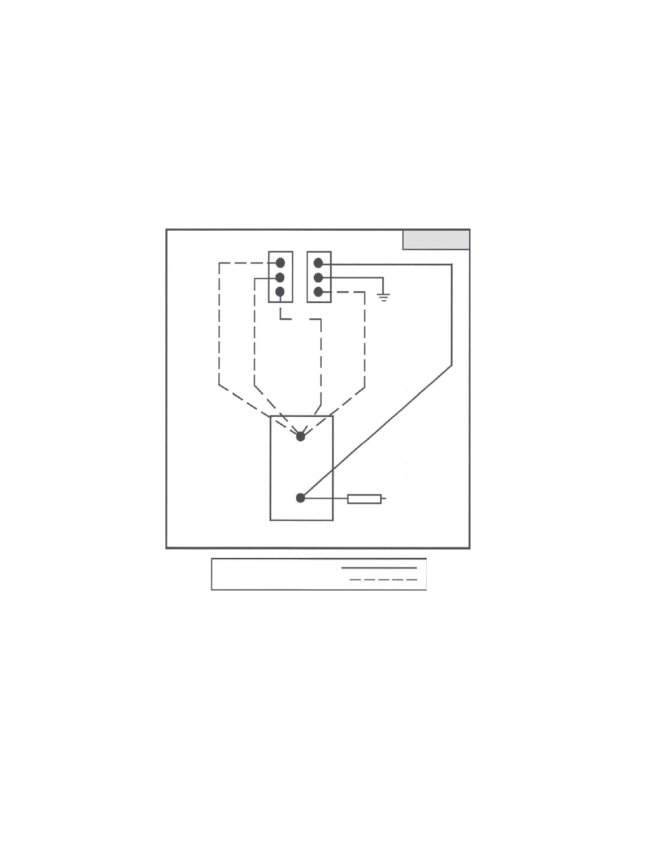
FIGURE D
1. Connect the Control wires from the Power/Control wire harness assembly to a switch or switches. To select
one of the 8 different flash functions, simply connect the Violet, Blue, Yellow, and Green wires to a switch in
the following combinations to produce the associated function when activated. See Figure D for Control Switch
connections. See Figure E for Control Wire combinations.
2. Connect Black wires to a reliable ground.(-)
3. Connect Red Power wires from the Power /Control wire harness assembly to the power source.(+) Attach a
15 amp in-line fuse to the red wire.
DIRECT CONNECTION
OPTIONAL CONNECTION
(+) 10-30 Vdc
VIOLET
BLUE
YELLOW
BLACK (-)
GREEN
RED (+)
15 Amp Fuse
SPST ON/OFF
SWITCH
(REAR VIEW)
CONTROL
POWER
See also other documents in the category Code 3 Lighting:
- 2004 LED Series Beacon (8 pages)
- 2004-2014 Tahoe Citadel (3 pages)
- 2015 Tahoe Citadel (8 pages)
- 2100 (16 pages)
- 21IF (12 pages)
- 21TR & 21TR Plus (18 pages)
- Solex MultiColor (12 pages)
- 235H Remote Strobe Power Supply (12 pages)
- 275 Series Beacon (8 pages)
- 300 Series Beacon (8 pages)
- 40, 41, 42 Series Perimeter Lights (8 pages)
- 410 Mini Bar (7 pages)
- 420 Mini Bar Series (16 pages)
- 550 Series Beacon (8 pages)
- 6 Pack LED Hide-A-Blast (8 pages)
- 80 Series Perimeter Lights (10 pages)
- 800 Series Software (8 pages)
- 87, 88, 89 Series Perimeter Lights (12 pages)
- 90 Series Strobe Beacon (8 pages)
- 950 Series Software (12 pages)
- Arch Beacon (12 pages)
- Astro L800, Star LL400, Nova L200 (8 pages)
- Caprice Side Marker LED light (4 pages)
- Chase (5 pages)
- Citadel Ford PI and Explorer (3 pages)
- Code 360 (24 pages)
- CommandStik (8 pages)
- CPS220 Remote Strobe Power Supply (8 pages)
- CPS690 Remote Strobe Power Supply (12 pages)
- D.O.T. Systems for 2010 Tahoe (4 pages)
- D.O.T. Systems for 2011 Dodge Charger (4 pages)
- D.O.T. Systems for 2011 Ford PI Utility and Explorer (4 pages)
- DashLaser (12 pages)
- DeckBlaster (10 pages)
- Defender (12 pages)
- Dual Head Wildcat (2 pages)
- E-10 Beacon Series (4 pages)
- Intrepid Headliner Mounting Bracket (2 pages)
- Essex (6 pages)
- Excalibur (24 pages)
- FM 9000 (12 pages)
- Ford PI B-Pillar Bracket (4 pages)
- Ford PI Citadel (8 pages)
- Frontier LED Mini Bar (8 pages)
- Halogen Duo Bulb Work Light (1 page)