Installation, Mounting options – Code 3 LED Perimeter Lights User Manual
Page 3
1.
Determine the mounting options to be used. Select the desired mounting location for the light head
assembly. The installation must accomodate the base gaskets. Refer to Figure 1 for gasket dimen-
sions.
Note: The gaskets are flexible. Do not use them for drill templates.
2.
Verify free clearance behind the mounting surface for wiring and fasteners.
3.
Using the appropriate template (Figures 2-4) cut the center opening for the wiring and install a
grommet (customer supplied). Use a drill bit sized for the appropriate thickness of the mounting
surface and a #10 sheet metal screw for drilling the screw holes. For example: for aluminum alloy
sheet metal .125" thick, a #23 (.154") drill size is recommended.
Note: If the unit is to be attached
with very high bond tape instead of screws then the screw holes need not be drilled. Clean the
mounting surfaces of the vehicle and the light head with isopropyl alcohol and dry thoroughly prior to
attaching tape.
4.
Route the vehicle power wires and allow a minimum of 3 inches of slack to protrude from the center
opening at each light head location. Use 18 AWG for wires up to 40 feet length, 16 AWG for wires up
to 70 feet length.
5.
Place the light head gasket (and bezel if used) over the light head location and run the vehicle power
wire slack through the center opening of the gasket. Refer to Figures 5 & 6.
6.
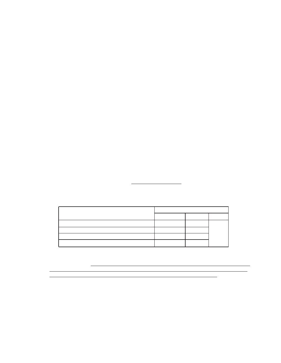
For Perimeter Lights refer to the section Flash Pattern Selection prior to finalizing the electrical
connections. Prepare the vehicle power wires and the light head’s wires with terminations of the
customer’s choice (not supplied). Waterproof connectors are recommended. Refer to the following
table for appropriate wiring connections.
7.
At the power source end of the cable determine if the cable length is acceptable. If a shorter length is
required, coil the cable and tie with an electrical tie.
8.
Verify proper light head operation by supplying electrical power to the system wires at the power
source end of the cable.
9.
Verify that the O-ring is properly seated onto the LED base unit.
10. Push the assembled electrical connectors through the center opening and into the vehicle.
11. Push the LED base unit (and bezel if used) into the gasket. The LED base unit is symmetric and does
not have a preferred top or bottom. Verify that the gasket (and bezel if used) is properly oriented.
These parts are labeled with “TOP” and their part numbers at the top and have a drain slot at the
bottom.
Installation
Connect the light head’s black and red wires to the vehicle system’s ground and positive (+12 or +24
VDC), respectively.
Note: For Perimeter Lights the white flash pattern selection wire must be
protected from contact with the system ground to prevent inadvertent changes to the flash
pattern. This can be accomplished by sealing or capping the end of the wire.
Wire Function
Red
White
Black
Models 45, 65, 85 - Perimeter Configurations
+12 or +24 Program
45STR & 65STR - LED STT, Red
Stop or Turn Tail Ground
45STA & 65STA - LED STT, Amber
Turn
none
Code 3 LED Perimeter Light Models
Mounting Options
There are three mounting options for the LED base unit:
1.
Attaching the LED base unit with high strength double-sided foam tape (customer supplied). This option
minimizes the piercing of the vehicle by requiring only a center wire hole.
2.
Attaching the LED base unit with four #10 x ¾” sheet metal screws.
3.
Attaching the LED base unit and lens together using four #6 x 1-½” sheet metal screws.
Options 1 and 2 allow removal of the outer lens without removing the base from the vehicle. Option 3 allows
removal of the entire unit from the vehicle with the removal of only four screws.
3