Installation – Code 3 Hide-A-Way User Manual
Page 3
Installation
1. Select the desired mounting for the Hide-A-Way strobe light assembly, keeping in mind that the strobe light
will share the same reflector as the headlight, brake light or turn signal lighting. Make sure that the Hide-A-
Way Strobe Light does not interfere with the proper operation of these lights see Figure 2.
2. Remove the reflector assembly from the vehicle. Choose a surface in the rear or bottom of the housing
which is as flat as possible and as close to the reflector focal point as possible see Figure 2. Using a one
inch diameter hole saw, cut a clearance hole for the Hide-Away strobe light in the housing as shown in Figure
3 (figure 3 may be used as a template). If installing the flange style tube, mark the location of the holes for
the two mounting screws, then with a .078 inch bit, drill both holes. Remove the backing from the flange
gasket to expose the adhesive. Carefully stick the gasket to the reflector assembly ensuring that it is properly
aligned with the three predrilled holes. Place the strobe light head flange onto the strobe tube assembly,
Twist clockwise until it stops.
3. Install the strobe tube assembly into the reflector as shown in Figure 5. Weather seal around the grommet
with a bead of silicone.
4. With the cable end located at the light head mounting location, route the three wire cable to the strobe
power supply. Allow three inches minimum slack at the light head to facilitate strobe tube assembly replace-
ment. Route the cable to the strobe power supply securing the cable along the way as necessary.
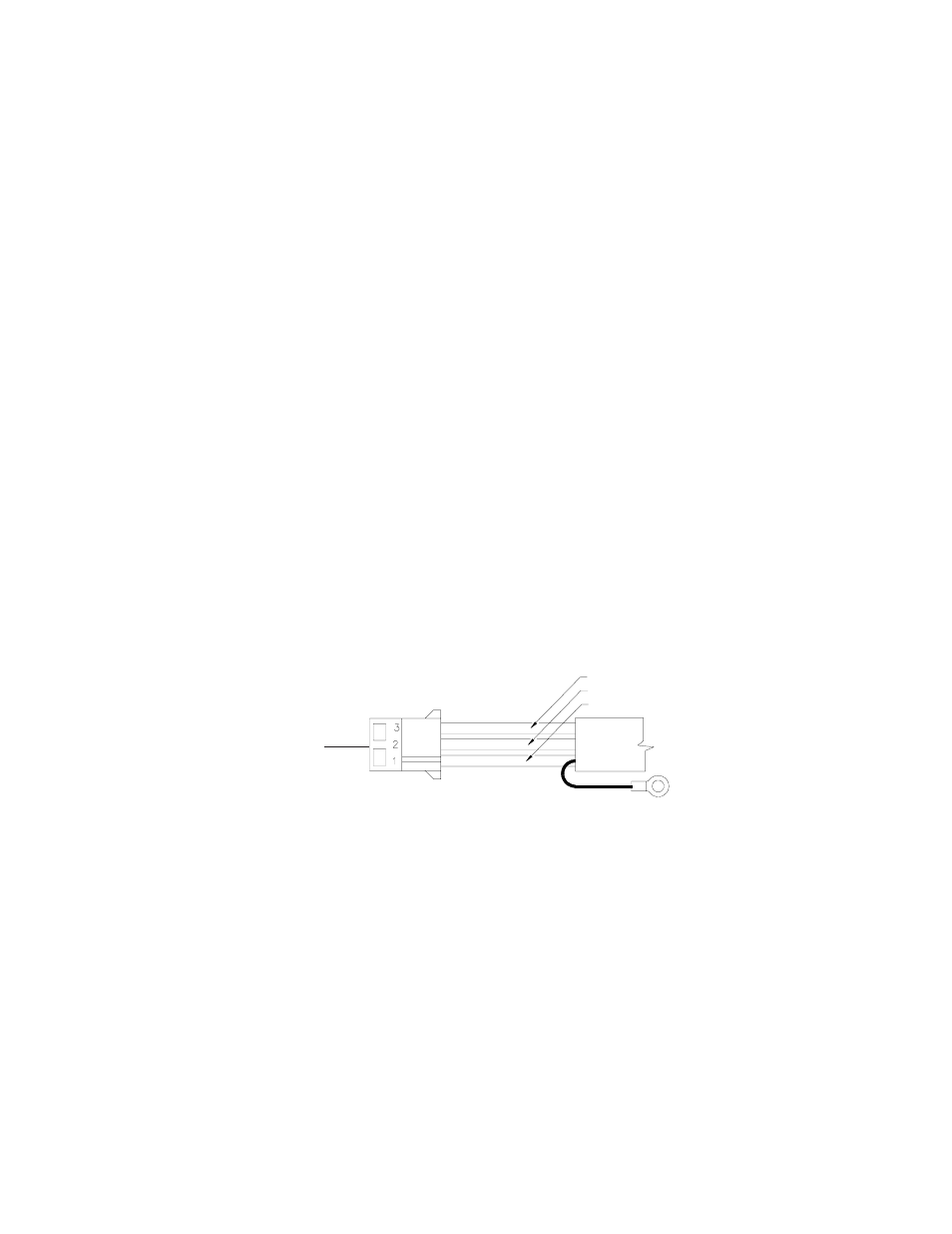
5. At the light head and power supply ends of the cable, insert the 3 AMP sockets into the AMP socket
housing as shown in Figure 4.
AT THE LIGHT HEAD END ONLY, Cut the shield wire flush with the jacket.
6. At the power supply end of the cable, determine if the cable length is acceptable. If a shorter length is
required, bundle the excess cable and secure it with a wire-tie. Crimp the #8 ring terminal to the shield wire
and attach to the nearest chassis grounded structure.
9. Test the strobe tube by connecting the cable to the Strobe Power Supply per the instructions with the power
supply.
SHIELD WIRE
FIGURE 1
THIS END TO POWER
SUPPLY
BLACK WIRE - CATHODE
WHITE WIRE - TRIGGER
RED WIRE - HIGH VOLTAGE
3