Control & power wiring – Code 3 CPS690 Remote Strobe Power Supply User Manual
Page 6
6
1. Connect the Control wires from the Power/Control wire harness assembly to a switch or switches. To select
one of the 12 different flash functions, simply press and release the pattern select switch until the desired
pattern is selected (see Figure F). The flash pattern may also be selected remotely by the operator by con-
necting a Normally Open (NO) Momentary Push Button Switch to pin 1 (Yellow Wire) of the control connector.
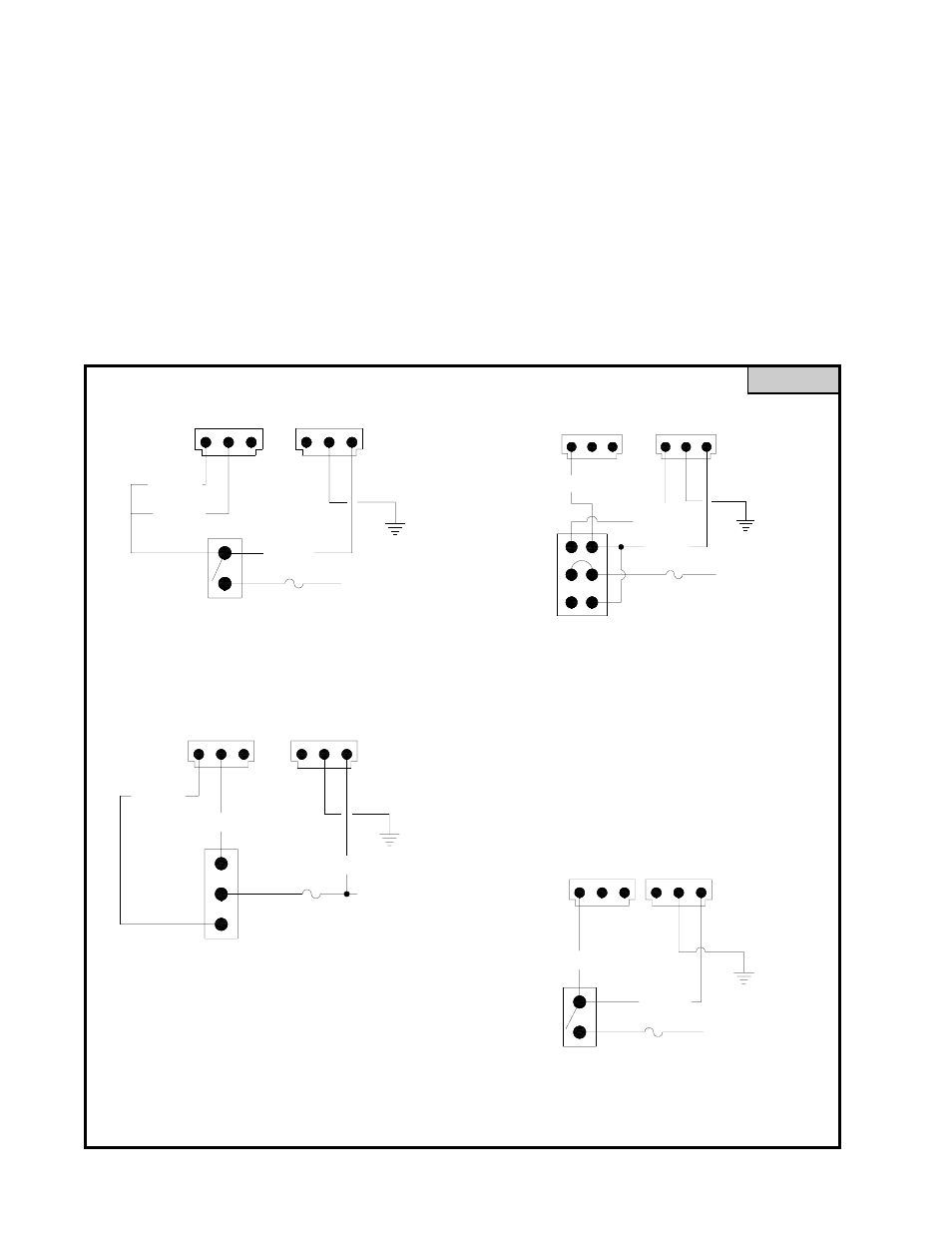
See Figure D for Control Switch connections. See Figure E for Control Wire combinations.
2. Connect Black wires to a reliable ground.(-)
3. Connect Red Power wires from the Power /Control wire harness assembly to the power source (+) through a
switch and an in-line fuse (15A for 12V operation or 7.5A for 24V operation) for the desired operation per Figure
D or Figure E.
CONTROL & POWER WIRING
FIGURE D
SELECTIVE SWITCHING
OF OUTLETS 1 AND 2 (only)
OR
OUTLETS 3/4 AND 5/6 (only)
IN HIGH POWER
15A FOR 12V
7.5A FOR 24V
OFF SWITCH
SPDT, CENTER
+
RED (+)
TO POWER
SOURCE
BLU (+)
GRN (+)
1
2
3
BLK (-)
1
2
3
(REAR VIEW)
4 OUTLETS ON-OFF SWITCHING
HIGH POWER
SPST 0N-OFF
SWITCH
7.5A FOR 24V
15A FOR 12V
TO POWER
SOURCE
+
1
BLU (+)
RED (+)
2
3
1
3
2
BLK (-)
CONTROL POWER IN
(REAR VIEW)
1
2
3
2
3
BLK (-)
RED (+)
1
GRN (+)
BLU (+)
SPST ON-OFF
SWITCH
15A FOR 12V
7.5A FOR 24V
+
SOURCE
TO POWER
6 HEAD, ON-OFF, HIGH POWER
(REAR VIEW)
DPDT CENTER
BLU (+)
OFF SWITCH
RED (+)
7.5A FOR 24V
15A FOR 12V
TO POWER
+
SOURCE
3
2
1
3
2
BLK (-)
1
VIO
(HI/LO)
4 HEAD, HIGH-OFF-LOW POWER
OFF SWITCH
(REAR VIEW)