Figure c, Figure b – Code 3 CPS690 Remote Strobe Power Supply User Manual
Page 5
5
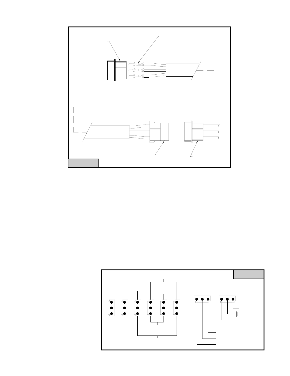
NOTE: IT IS IMPORTANT TO FOLLOW THE CORRECT COLOR CODE
WHEN INSERTING THE PINS INTO THE AMP 3 PIN CONNECTORS.
4. Connect the cables to the strobe light heads.
5. Next, plug the other end of the cable into the Light Head socket (output) on the CPS690 strobe power
supply. The location of the cable for each light head attached to the CPS690 will be determined by the flash
mode selected. (see figure E on page 6)
POWER/CONTROL WIRE HARNESS ASSEMBLY
The Power/Control wire harness assembly consists of two 3 pin AMP style connectors with: 1 red, 1 black, 1
violet, 1 yellow, 1 blue and 1 green (see figure C). The Power/Control harness assembly must be connected to
the power/control socket(s) located on the CPS690 strobe light power supply. Use 18 gauge wire to extend the
control harness wires to a customer supplied switch to complete the installation.
IMPORTANT: To extend the
power (+) and ground (-) wires,
use the following as a guide.
1 to 10 ft. use 16AWG wire
10 to 20 ft. use 14AWG wire
20 to 30 ft. use 12AWG wire
30 to 50 ft. use 10AWG wire
3
2
1
2
1
3
2
1
3
2
1
3
2
1
3
2
1
3
3
1
2
1
2
3
SIMULTANEOUS
FLASH
SIMULTANEOUS
FLASH
ALTERNATING
FLASH
ALTERNATING
FLASH
RED (+)
BLK (-)
VIO [HP (NC)]
CONTROL
POWER IN
YEL (+) PATTERN SELECT
GRN (+) 1L/2L
BLU (+) 3/5L or 4/6L
1
2
3
4
5
6
[LP (+12VDC)]
FIGURE C
SHIELD WIRE CONNECT TO
CHASSIS GROUND
Male Amp connector
to be mated with the
Amp output socket on
the Power Supply.
3
2
1
2
3
1
Amp wire harness
attached to Strobe
light head.
Female Amp
connector.
3
1
2
Insert wires with male pins into the
proper locations in the male Amp
connector:
RED WIRE - POSITION 1
BLACK WIRE - POSITION 2
WHITE WIRE - POSITION 3
FIGURE B