Major calibration and repair – CDI Torque TORQUE WRENCHES Micro-Adjustable Click Type User Manual
Page 12
Page 8
9. Pull the lock ring down, while applying a light force towards the wrench (to prevent
handle disengagement) and turn handle until handle “0” mark is aligned to the
centerline of the scale.
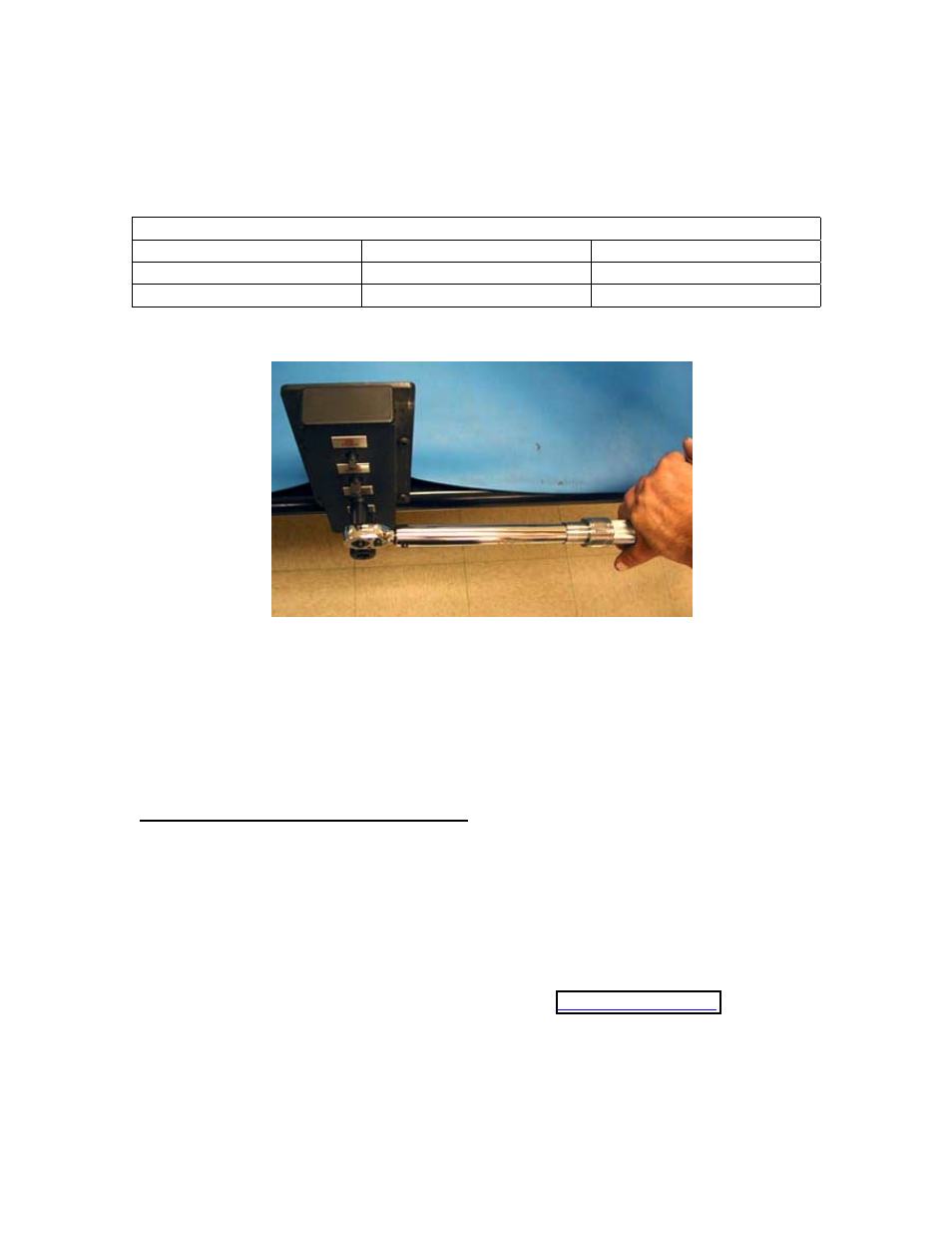
10. Tighten the hex flange nut (B) with a 200 in. lb. torque wrench as follows:
Handle Locking
Torque Wrench Ranges
Hex Flange Nut Size
Torque Ranges
50 in. lb. to 250 in. lb.
3/8”
35 to 40 in. lb.
75 ft. lb. to 1000 ft. lb.
7/16”
90 to100 in. lb.
11. Retest the wrench for accuracy (steps 1 through 4). If the wrench is not within
specified accuracy requirements repeat steps 5 through 10 or the wrench may require
a major calibration.
MAJOR CALIBRATION AND REPAIR
These instructions are to be used for the major calibration. Major calibration requires the
wrench to be partially disassembled from the front removing the ratchet or drive
mechanism, to inspect the internal component parts for contaminates, damage and/or
wear. Replacement parts are normally required. Each wrench model has an Exploded
Illustration that lists the component parts and shows assembly particulars. The exploded
illustration must be used as a guide for purchasing CDI Torque Wrench component parts.
Contact CDI Sales Department at (626) 965-0668 or
for
Exploded Illustrations for a particular torque wrench model and/or to purchase
component parts needed for repairs.