Ab c d, Fig.3, 3 details of rd65 communication interface – Salter Brecknell RD-65 Remote Display User Manual
Page 11
9
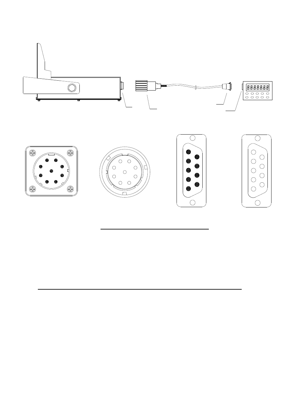
3.3 Details of RD65 communication interface
Host
Wires
RD65
A
B
C
D
1
2
3
4
5
6
7
8
9
1
2
4
6
5
3
9
7
8
1
2
3
4
5
6
7
8
9
1
2
3
4
5
6
7
8
9
A
B
C
D
Fig.3
Connection between RD65 and Host
A ---- 9 pin socket(pin) on RD65
B ---- 9 pin plug (hole) on one end of connected wire
C ---- DB9 plug (pin) on another end of connected wire
The Color of wires on B and C interface cable:
Connector “B” Pin# Color Connector “C” Pin#
1 ------------
Red
------------
1
2 ------------
Black
------------
2
3 ------------
Yellow
------------
3
4 ------------
Green
------------
4
5 ------------
Blue
------------
5
6 ------------
White
------------
6
7-9 -----------
not used
------------
7-9
See also other documents in the category Salter Brecknell Scales:
- PB500 (4 pages)
- PB250 (12 pages)
- MB2610 (4 pages)
- MBS Series (14 pages)
- 302BP (6 pages)
- 304BP (26 pages)
- 308BP (27 pages)
- APD-100 (36 pages)
- CB100 (8 pages)
- ESA Series (14 pages)
- LPS30 (18 pages)
- PC150 (13 pages)
- SP60 (9 pages)
- 3700LP (20 pages)
- C3235 (16 pages)
- C3255 (18 pages)
- C3225 (40 pages)
- B140 (32 pages)
- B120 (19 pages)
- B130 (22 pages)
- 610 (23 pages)
- 630 (24 pages)
- 650 (43 pages)
- B220 (24 pages)
- B225 (44 pages)
- CS Series Crane (12 pages)
- 3800LP Series Calibrated with SBI-505 LED Indicator (22 pages)
- 405 (12 pages)
- LPS150 (30 pages)
- GP100 (13 pages)
- S100 (17 pages)
- PS150 (15 pages)
- S122 (63 pages)
- 6702 (28 pages)
- 6712 (24 pages)
- PS250 (28 pages)
- PS500 (19 pages)
- PS1000 (38 pages)
- PS3000HD (18 pages)
- SBI140 (35 pages)
- SBI100 (34 pages)
- SBI-521 (82 pages)
- 200 Series (47 pages)
- 200SL (2 pages)
- 400ES (30 pages)