Diagram 1, Diagram 2, Note – Arc Machines 415 WDR User Manual
Page 37: Model 415 operation manual
Model 415
Operation Manual
Document No. 740084
Revision N
32
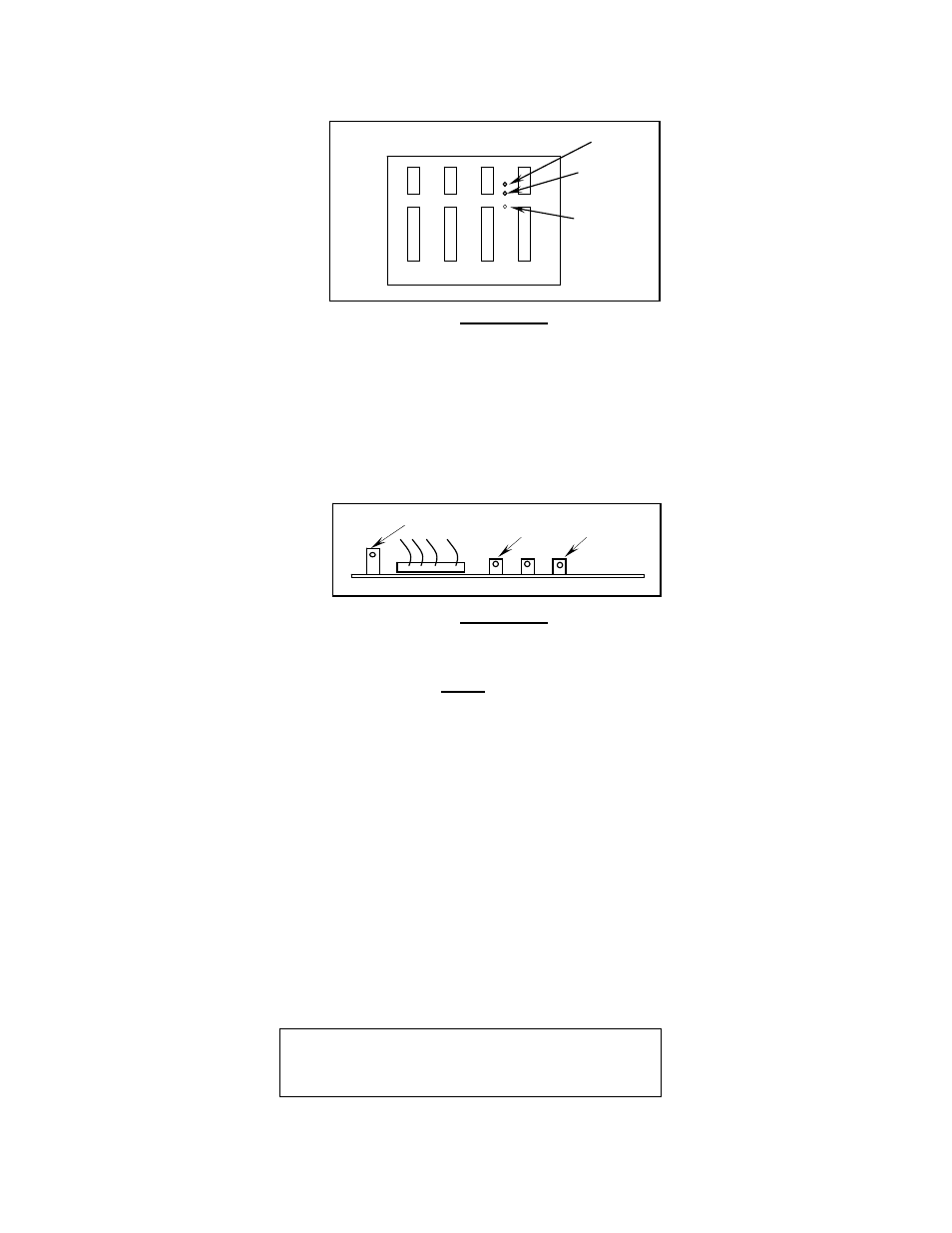
POS.
NEG.
R9
ADJ.
B 0/1 C 0/1 D 0/1
DIAGRAM 1
5.5
POSITION FEEDBACK REFERENCE CALIBRATION
1.
Locate the PCB labeled INTERFACE on the Servo Mounting plate (13D150317-01).
2.
Insert the positive probe of the DMM into TP-1 and negative probe into TP-2 (Diagram 2).
3.
DMM should read 5.000 VDC
0.010 VDC. If out of tolerance adjust the R-4 trim pot.
DIAGRAM 2
5.6
CURRENT CALIBRATION
NOTE
True verification of M-415 Power Supply current output for Quality Control purposes must be done
with an External Calibration Shunt that is calibrated by an independent agency to a national
standard. An External shunt adequate for this use is available through AMI as an option.
This procedure is written to include both calibration using internal measurements and for the
external shunt option provided by AMI.
A weld schedule is required for the following calibrations. The first time a calibration is done, it will
be necessary to CREATE a Calibration Weld Schedule. Each section will outline all pertinent
schedule elements need. It is recommended that a single schedule be made with each calibration
section programmed as a separate pass.
1. Insure that the Weld Head or Hand Torch is connected per section III of the M415 Operation
Manual. (Tip: Use a copper block as a work piece.)
2. To calibrate Current the user will need to have a Weld Schedule in the Library for the M-415 and
applicable Weld Head, (Pass 1). If using the optional AMI Carbon Load or Hand Torch Welding
voltage must be maintained between 9 and 15 volts (approximately 1/8th inch Arc Gap). Also
the template will have the following differences:
TP-2
TP-1
R4 ADJ.
THE STUBOUT MODE MUST BE SET TO OFF
THE GAS FLOW MUST BE SET TO 0 CFH
THE START MODE SHOULD BE SET TO RF