Wiring diagram, Dv power vent system, Synetek ignition module) – Vermont Casting 7PDVS User Manual
Page 14
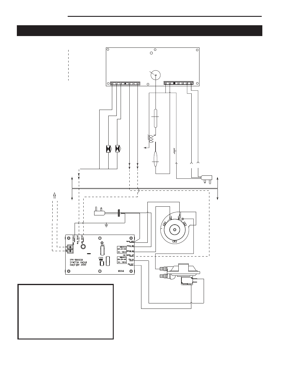
DV Power Vent System
14
10003262
COM
NO NC
BLUE
YELLOW
WHITE
RTN
HOT
BLACK
WHITE
GREEN
OR ON/OFF SWITCH TO W
ALL
THERMOST
AT
BUSHING
WIRE SPEC.:
FIELD SUPPLIED
MINIMUM INSULA
TION 2/64"
18 A
WS SOLID, LOW VOL
TAGE
& INST
ALLED WIRES
Power V
ent Kit
LED
J2
120V
ac Hot
120V
ac Rtn
Fan Rtn
Fan Hot
Key
Flame Sense
Chasis / Burner Ground
1/4” Male T
ab
J1
24V
ac Hot (R)
Thermostat (W)
Key
Pilot V
alve Hot
Main V
alve Hot
Pilot / Main V
alve Rtn.
CFM 10007939
Synetek
Ignition Module
L1
120/220 V
ac (Hot)
L2
120/220 V
ac (Rtn)
Ignitor
Sensor
Burner Ground
Main V
alve
Pilot V
alve
Fireplace
Power V
ent Kit
Fireplace
Hose
Wiring Diagram
(Synetek Ignition Module)
LED Codes
ON Normal operation
2 Flash Ignition trial lockout
3 Flash Flame loss lockout
5 Flash 120V AC reversed polarity
or board not sensing ground
Steady Flash Flame detected out of al-
lowed sequence or internal
fault, hardware error
- RHE32 (38 pages)
- R24CFL (14 pages)
- 3399 (38 pages)
- DVRT41 (48 pages)
- Montpelier Wood Insert MEAD3CB (12 pages)
- Insert Studio LHER30 (8 pages)
- SR18SHK (16 pages)
- PerfectView 33LDV (4 pages)
- SC42 (24 pages)
- 3030 (26 pages)
- EF22 (16 pages)
- DV360 (56 pages)
- DV580 (60 pages)
- SA24SKHRN (20 pages)
- SHR42A (24 pages)
- VL21 (20 pages)
- DEF (11 pages)
- 7TDVP8 (3 pages)
- DVRT39 (50 pages)
- HiStyle DVBR42RN (2 pages)
- ICVCTK01 (12 pages)
- RFSDV24 (36 pages)
- HEF22 (12 pages)
- NV360 (24 pages)
- NVBC42 (24 pages)
- VCEF33 (12 pages)
- Romanesque HG004 (4 pages)
- Designer Select Series (4 pages)
- OD24SHKN (12 pages)
- BR36 (24 pages)
- CVR36 (28 pages)
- H33BDVRRNP (32 pages)
- 2080 (24 pages)
- DEF33 (16 pages)
- Allura-Fire Electric Fireplaces EF26 (1 page)
- EF26 (2 pages)
- DBR33 (32 pages)
- DEF33CE (12 pages)
- HEF33 (14 pages)
- D232 (28 pages)
- RHEDV25 (38 pages)
- Allura-Fire Markham Combo MKWWH33 (2 pages)
- BREF42R (24 pages)
- DBT39 (34 pages)
- CR36R (24 pages)