Craftsman 247.799620 User Manual
Page 8
Attention! The text in this document has been recognized automatically. To view the original document, you can use the "Original mode".
• Squeeze the clamp on the drawstring and pull the
drawstring tight. Release the clamp.
Drive
FIGURE 5.
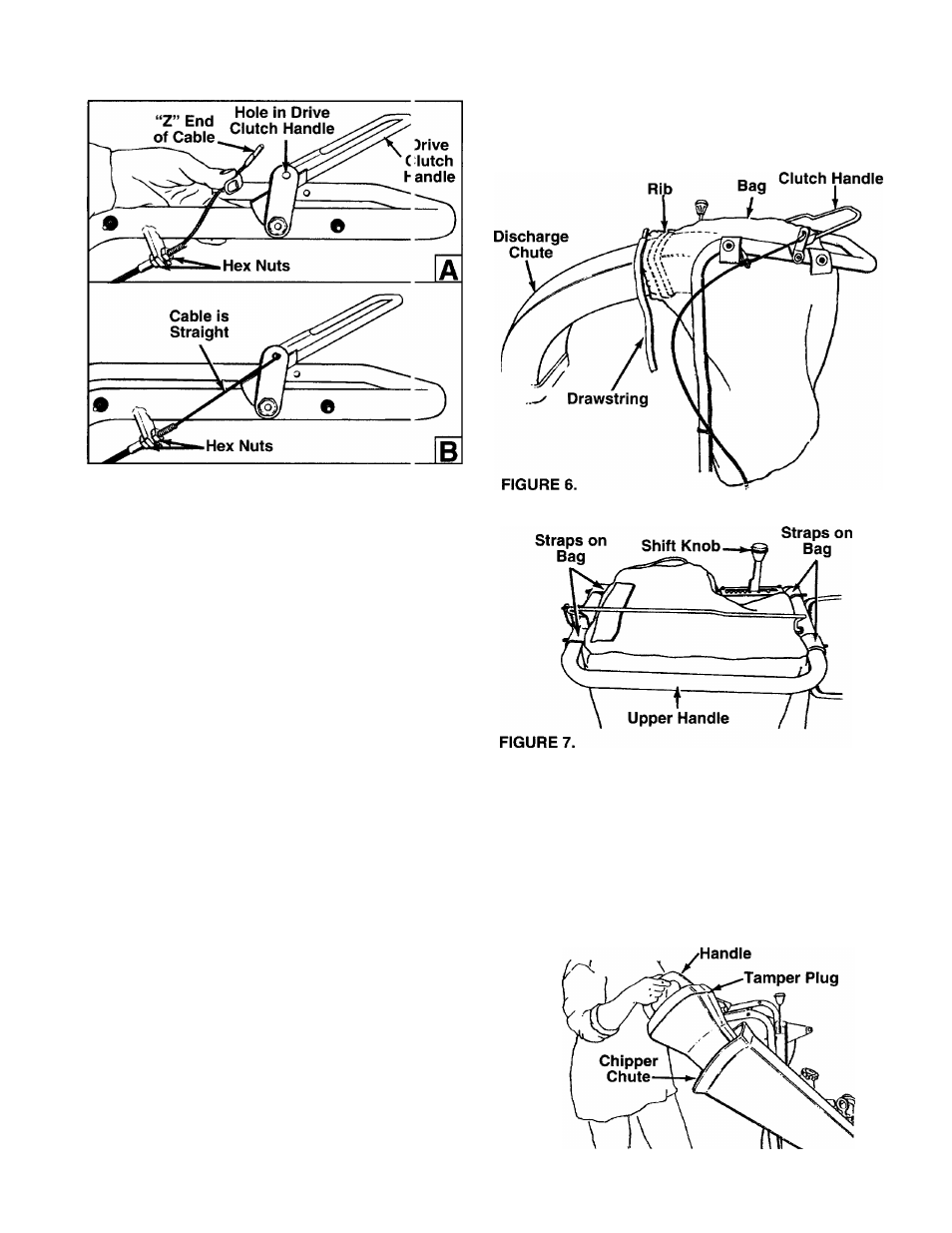
ADJUSTING THE CLUTCH CABLE
• While adjusting the hex nuts at the cable t racket,
make sure that there is no slack in the cable, but
the cable is not tight. See figure 5B. Do not over
tighten the cable.
To check the clutch adjustment, proceed as fol ows.
• Push the chipper-vacuum backward and lorward
with the drive clutch handle released. It should
move freely. If it does not, loosen both hex nuts at
the cable bracket. See figure 5B. Turn botlom nut
counterclockwise to loosen the cable.
• Holding against the upper handle, engage tf e drive
clutch handle and try to push the unit backward
and forward. The wheels should lock up.
• If the wheels do not lock up, loosen both h jx nuts
at the cable bracket. Turn front nut clock vise to
tighten the cable.
• Recheck the adjustment. Tighten both the h 3X nuts
when you have adjusted it correctly.
INSTALLING THE SHIFT KNOB
• Thread the shift knob onto the end of tte shift
lever.
ATTACHING THE BAG
• Place bag inside the handle assembly. £ lip the
opening on the bag over the discharge chute. Make
sure that it is over the rib on the discharge chute.
See figure 6.
• Place the four straps on top of the bag o rer the
upper handle, hooking them on the studs. See fig
ure 7. Make sure that the bag goes under tfe drive
clutch handle.
INSERTING THE TAMPER PLUG
The handle of the tamper plug must be vertical.
• Match the angle of the tamper plug with the angle
of the chipper chute. See figure 8.
• Insert the tamper plug into the chipper chute.
NOTE: Tamper plug should remain in the chipper
chute whenever the chute is not in use.
FIGURE 8.