Craftsman 247.799620 User Manual
Page 16
Attention! The text in this document has been recognized automatically. To view the original document, you can use the "Original mode".
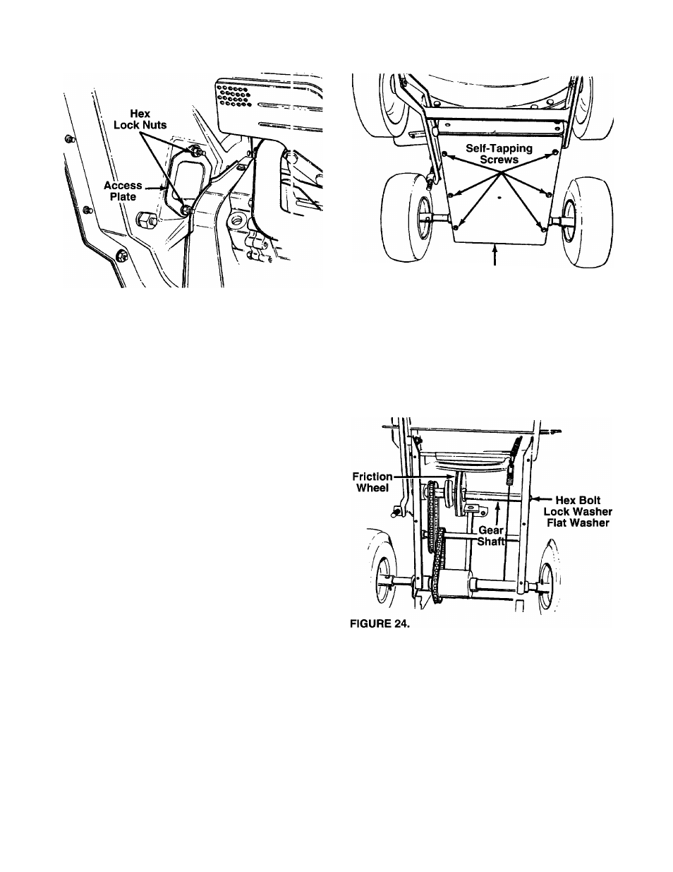
FIGURE 22.
A
WARNING: MAKE SURE TO V/EAR
HEAVY DUTY GLOVES FOR THIS JOB.
WHILE ACCESSING THE CHIPPER
BLADE, YOU MAY HAVE TO CLEA vl THE
SCREW
HEAD
OF
DUST
AND
SHREDDED PARTICLES TO ENABLE
THE ALLEN WRENCH TO OPERATE.
HANDLE THE WRENCH CAREFULLY SO
THAT YOU DO NOT CUT YOUR HAND
ON THE CHIPPER BLADE.
• Locate one of the chipper blades in the c ccess
plate opening by rotating the impeller asserr bly by
hand. Remove the blade using a 3/16" aiien
wrench on the outside of the blade and 1/2" \/rench
on the impeller assembly, inside the hojsing.
Torque hardware to 250-350 inch pounds.
• Remove the other blade in the same m;inner.
Replace or sharpen blades. If sharpening, make
certain to remove an equal amount frorr each
blade. Reassemble in reverse order.
NOTE: Make sure that the blades are reasse mbied
with the sharp edge facing upward, as viewe
i
from
the access plate opening.
CHANGING THE FRICTION WHEEL RUBBER
The rubber on the friction wheel is subject to wear
and should be checked after 50 hours of operation,
and periodically thereafter. Replace friction wheel
rubber if any signs of wear or cracking are found.
• Drain the gasoline and oil from the ch pper-
vacuum.
• Tip the unit backward so it rests on the handl 3S.
• Remove the frame cover by removing eight self
tapping screws from underneath the chipper-
vacuum. See figure 23. (Only six of the eight
screws are shown in the figure.)
Frame Cover
FIGURE 23.
Remove the gear shaft from the unit by removing
the hex bolts, lock washers and flat washers from
each side of the frame. See figure 24. Hold the fric
tion wheel assembly, and slide the gear shaft out of
the unit toward the right side.
• Remove the six screws from the friction wheel
assembly (three from each side). Remove the fric
tion wheel rubber from between the friction wheel
plate.
• Reassemble new friction wheel rubber to the fric
tion wheel assembly, tightening the six screws in
rotation and with equal force.
• Slide the friction wheel assembly up onto the shift
mechanism, then slide the gear shaft back into the
unit. Reassemble in reverse order.
• Readjust the clutch cable. Refer to adjustment sec
tion.
16