Adjusting the clutch cable, Adjusting the shift rod – Craftsman 247.799620 User Manual
Page 17
Attention! The text in this document has been recognized automatically. To view the original document, you can use the "Original mode".
ADJUSTING THE CLUTCH CABLE
To adjust the clutch cable, refer to the “Clutch Cable
Adjustment” section of Assembly Instructions.
REPLACING THE BELT
A
WARNING: Disconnect the spark plug
wire and move away from the spark plug.
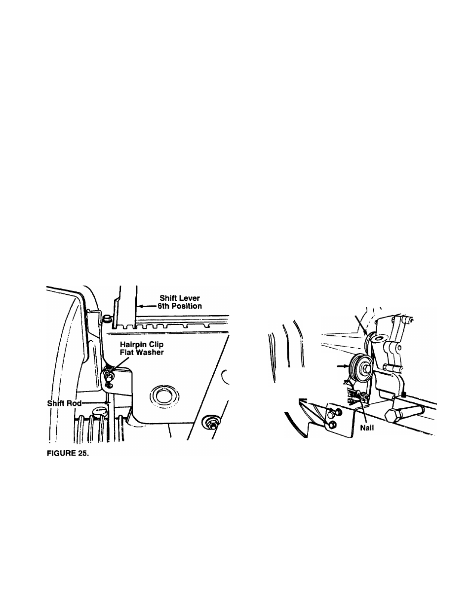
ADJUSTING THE SHIFT ROD
If the shift rod is at 1 or R1 position, but the unit does
not show any forward or reverse movement as the
case may be, the shift rod wiil need to be adjusted.
See figure 25.
• Remove the bag from the unit.
• Remove the hairpin ciip and the fiat washer from
the upper end of the shift rod.
• Pull the ferrule out of the hole in the shift lever.
Make sure that you do not displace the wave wash
er from the ferrule.
• Place the shift iever in the 6th position which is aii
the way to the left.
• Push down on the shift rod.
• Thread the ferrule up or down the shift rod two
turns so that the ferrule lines up with the upper hoie
in the shift lever.
• Secure the ferrule to the shift lever using the fiat
washer and the hairpin clip.
• Remove the plastic beit cover on the front of the
engine by removing two self-tapping screws. Refer
to figure 21.
• Drain the gasoiine and oii from the chipper-
vacuum.
• Tip the unit backward so that it rests on the
handies.
• Remove the frame cover by removing eight self
tapping screws from underneath the chipper-
vacuum.
• Remove the idier puiley bracket as foiiows. See
figure 26.
• Take the tension off the belt by pivoting the idler
pulley toward you, and line up the holes in the idler
bracket assembly. Insert a nail or similar object
through the holes to hold the idler pulley in this
position.
• Remove three self-tapping screws, and lift off the
idler bracket assembly.
Engine Pulley
Idler
Bracket
'Assembl
m \
Self-Tapping
Screws
FIGURE 26.
Idler
Pulley
a
• Remove the hex bolt and lock washer from the
engine pulley. See figure 26. Slip the engine pulley
off the engine shaft, and remove the belt from the
pulley.
• Loosen the nut on the stop bolt until there is clear
ance between the support bracket and the friction
wheel disc. See figure 27.
• Slip the belt between the friction wheel and friction
wheel disc. Remove and replace belt. Reassemble
following instruction in reverse order.
NOTE: The support bracket must rest on the stop bolt
after the new belt has been assembled.
17