Service and adjustment – Craftsman 486.248371 User Manual
Page 18
Attention! The text in this document has been recognized automatically. To view the original document, you can use the "Original mode".
SERVICE AND ADJUSTMENT
]
A
CAUTION: Before servicing or adjusting
the snow thrower, shut off the engine, remove
the spark piug wire(s), set the parking brake
and remove the key from the tractor ignition.
REPLACING AUGER BELT
•
Disengage the tractor's attachment dutch.
•
Lower the snow thrower to the ground.
•
Remove the attachment pin.
•
Lock the snow thrower's iift handie in the down
position to decrease beit tension.
•
Reiease the spring tension from the auger beit idier
arm on the bottom of the ciutch/idier assembly.
•
Remove the auger drive belt from the ciutch/idier
assembly and from the spiral auger housing.
•
Install new belt over top of large auger drive pulley
and under the two side idler pulleys. Twist the belt 1/4
turn to seat the "V" of the belt in the groove of each
idler pulley. Refer to figure 23 on page 14.
•
Assemble the belt onto the ciutch/idier assembly.
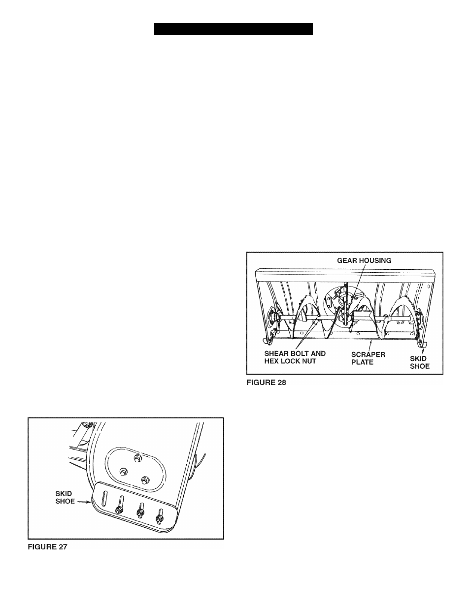
SKID SHOE ADJUSTMENT
•
The skid shoes are mounted on each side of the spiral
auger housing. They regulate the distance the scraper
plate is raised above the plowing surface. When
removing snow from a gravel driveway or and uneven
surface, it is advisable to keep the scraper plate as
high above the surface as possible to prevent possible
damage to the spiral auger. On blacktop or concrete
surface, keep the scraper plate as close to the surface
as possible.
•
Raise the snow thrower off the ground and place a
block under each end of the scraper plate. Loosen the
six hex nuts securing the skid shoes to the housing.
Adjust the skid shoes up or down and retighten the
nuts securely. Adjust both skid shoes to the same
height to keep the housing and the scraper plate level.
See figure 27.
LIFT RELEASE CABLE ADJUSTMENT
•
If the lift rod does not lock the snow thrower securely
in the transport position, loosen the upper hex nut on
the lift bracket a few turns and tighten the lower hex
nut. Refer to figure 16 on page 12.
•
If the lift rod fails to unlock completely to lower the
snow thrower, loosen the lower hex nut on the lift
bracket a few turns and tighten the upper hex nut.
Refer to figure 16 on page 12.
SPIRAL AUGERS
•
The spiral augers are secured to the auger shaft with
two shear bolts and nylock nuts. If you hit a foreign
object or if ice jams the augers, the snow thrower is
designed so that the bolts will shear.
•
If the augers will not turn, check to see if the shear
bolts have sheared. See figure 28. Two replacement
shear bolts and nylock nuts have been provided with
the snow thrower. For future use order part number
710-0890A shear bolt and number 47810 nylock nut.
18