Craftsman 486.248371 User Manual
Page 11
Attention! The text in this document has been recognized automatically. To view the original document, you can use the "Original mode".
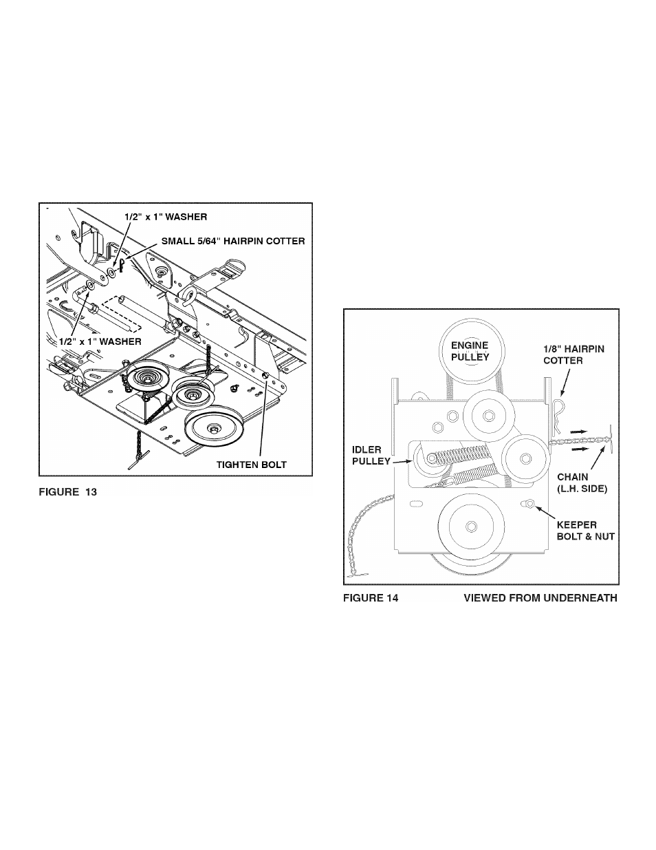
STEP 13 (SEE FIGURE 13)
•
Assemble a 1/2" x 1" washer onto the bent end of a
support link and then insert the threaded end into a
support tube and the bent end into the rear hole in
a front mounting plate, Assemble another 1/2" x 1"
washer onto the end of the link and secure it with
a small 5/64" hairpin cotter. Repeat for the other
support link.
•
Tighten the bolt and nut in each rear frame bracket.
•
Tighten the bolt and nut in each support link.
•
Tighten the jam nuts so that all looseness is
eliminated from the support links and support tubes.
STEP 14: (SEE FIGURE 14)
•
Remove the belt guard for the PTO pulley on the
tractor. Refer to "Cutting Deck Removal" in the
SERVICE AND MAINTENANCE section of your
tractor Operator's Manual.
•
Install the drive belt onto the tractor's PTO pulley. You
may need to temporarily lift the belt from the large
pulley on the clutch idler assembly.
•
Reinstall the belt guard for the tractor's PTO pulley.
Be sure the belt guard is installed in the notch on the
side of the tractor's electric clutch.
•
Place tension on the belt by pulling the left side
tensioning chain out as far as the 3/32" hairpin
cotter will allow. Secure the chain in this position by
inserting a 1/8" hairpin cotter through the chain.
A
DO NOT start the engine until the PTO
pulley belt guard has been reinstalled. The
tractor's electric clutch could be damaged.
11