Installation, C“rpp 10 connect door arm to trolley, One-piece door installation – Craftsman 139.53625SR User Manual
Page 16
Attention! The text in this document has been recognized automatically. To view the original document, you can use the "Original mode".
Installation
C“rpp 10 Connect Door Arm to Trolley
■«j I C-r lU Follow only those instructions which apply to your door type.
SECTIONAL DOOR INSTALLATION
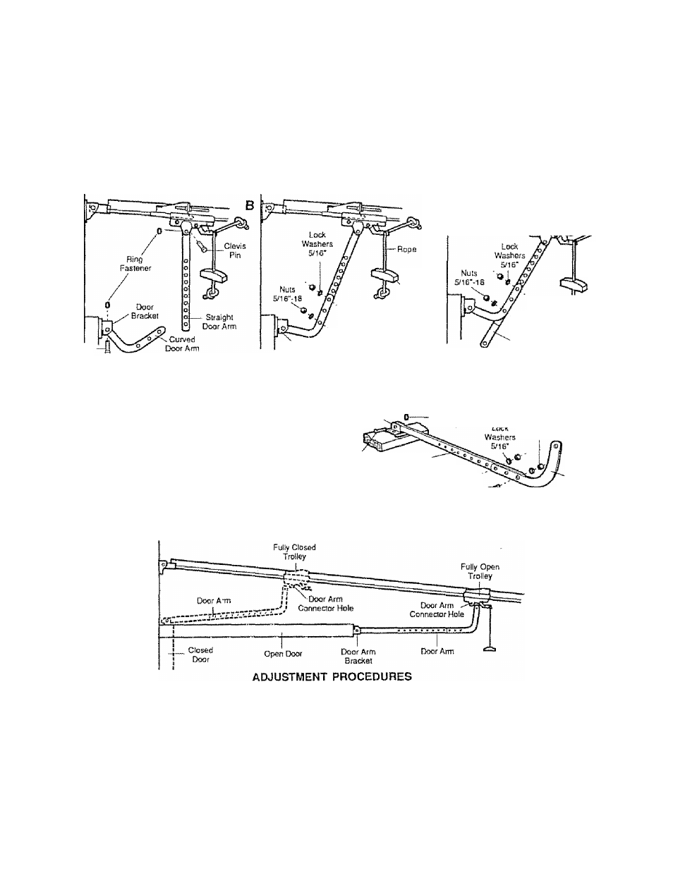
Make sure garage door is closed tight. Pull the emergency release handle to disconnect the trolley. Manually move
outer trolley back to the center of inner trolley as shown In Figures A, B and C.
FIG A: Fasten straight door arm section
to outer trolley with a clevis pin Secure
the connection with a ring fastener.
Fasten curved section to door bracket in
the same way.
A
FIG B: Bring arm sections together Find
two pairs ol holes that line up and join
sections.
Select holes as far apart as possible to
increase door arm rigidity
Ctevis Pin
FIG C: If holes in curved arm are ABOVE
holes in straight arm, disconnect straight
arm. Cut about 6" from the solid end.
Reconnect to trolley wilh CUT END
DOWN as shown,
Bring arm sections together Find two
pairs of holes that line up and Join with
screws, lock washers and nuts
Door Bracksi
N Saewa
5/ir-iax7r8"
Emergency
Reisase
Handle
X
Screws
S/
16
‘-
1
8x7/8'
- Cut This End
Proceed to Step 1, page 17. Trolley will rs-engage automatically when opener is operated.
ONE-PIECE DOOR INSTALLATION
ASSEMBLE DOOR ARM: Fasten straight and curved door
arm sections together to longest possible length. With door
closed, connect straight door arm section to door bracket
with a clevis pin. Secure with a ring fastener.
Door
Bracket'
. Riris
Fastener
Nuts
s/i6"-te
Clevis Pin
Straight '
Arm
Screws
5/16'-10x7/8---------
Curved
Door Arm
Before connecting door arm to trolley, limits of travel most be adjusted on one-piece doors. Limit adjustment screws
are located on left side panel as shown In illustralion on Page 17. Follow procedures below.
OPEN DOOR ADJUSTMENT
Decrease UP limit Turn UP limit adjustmenl screw counletcSock-
wise 4 complete turns.
Press Lighted Walt Push Button. Trolley will travel to full open.
Manually raise door arm to open position {paralSel to Itoor) and
ItIt door arm to trolley The arm should touch trolley just in back
of door arm connector hole as shown in solid line drawing. If arm
does not extend far enough, adjust limit further, One full turn
CLOSED DOOR ADJUSTMENT
Decrease DOWN limit. Turn DOWN limit adjustment screw dock-
wise 8 complete turns
Press Lighted Wall Push Button. Trolley will travel to lull closed.
Manually close door and lift door arm to trolley. The arm should
touch trolley just ahead of door arm connector hoie as shown in
dolled line drawing. If arm is behind the connector hoie, adjust
limit further One lull turn equals 2" of door travel
equals 2" of door travel.
CONNECT DOOR ARM TO TROLLEY; With door closed, join curved arm to connector hole in trolley with remaining clevis pin,. Secure
with ring fastening pin. NOTE: It may be necessary to lift door slightly to make connection.
Run opener through a complete travel cycie. if door has a slight ‘downward’ slant in full open position, decrease UP limits until door
is paraiiet to floor,
16