To install blade guard, Assembly – Craftsman 315.228110 User Manual
Page 20
Attention! The text in this document has been recognized automatically. To view the original document, you can use the "Original mode".
ASSEMBLY
TO INSTALL BLADE GUARD
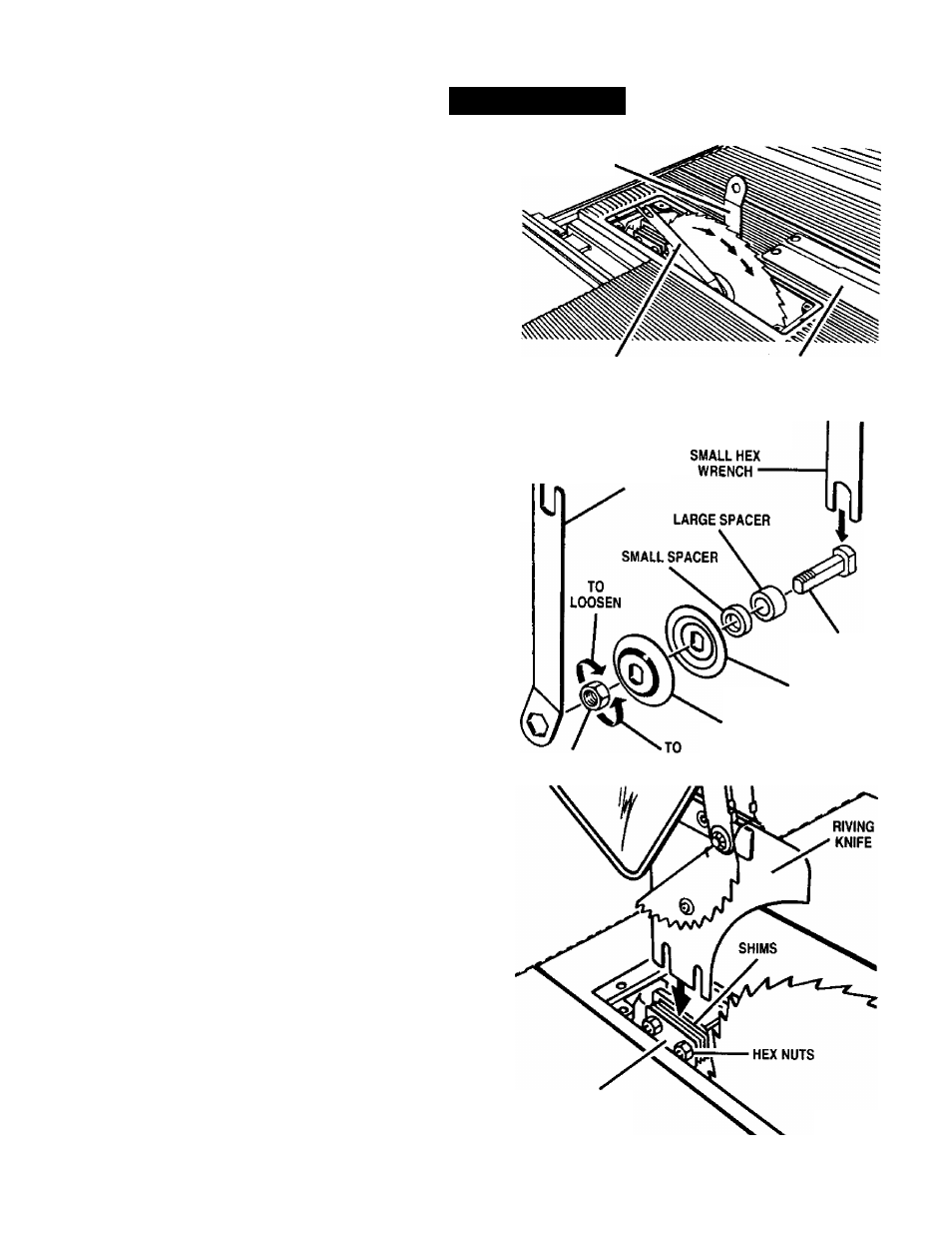
■ To install the blade guard, first remove the three
screws holding the throat plate in place. Remove
the throat plate.
See Figure 17.
■
Make sure that the locking lever is securely pushed
to the left. Raise the blade arbor to its full height by
turning the blade adjusting handle clockwise.
■ Move the locking lever to the right for Angle mode.
Slowly turn the blade adjustment handle to put the
blade at 30 degrees. The handle will "pop out"
slightly as it engages the clutch.
■
Holding the blade adjusting handle with one hand,
use the other hand to push the locking lever firmly
to the left to lock the angle.
■ Using the small hex wrench, install the blade guard
by loosening the two attachment hex nuts enough
to slide the riving knife down between the shims.
Do not remove the hex nuts. See Figure 19.
Partially retighten the two attachment nuts. Check
the blade and riving knife alignment.
■ Correctly align the blade and riving knife as shown,
repeating step 5 as needed. Tighten attachment
nuts securely. If riving knife is not positioned
correctly, with blade up, it could contact saw table
when blade is lowered and restrict blade elevation.
■ Blade alignment with the riving knife can be
adjusted for different blade widths. Refer to
Settings and Adjustments
in the Operations
Section.
■ Check the blade guard assembly for clearances
and free movement. Reinstall the throat plate into
the opening, lower the blade and secure the three
attachment screws. Tighten the screws securely.
SMALL HEX
WRENCH
LARGE
HEX WRENCH
THROAT PLATE
Figure 17
NOTE; PLACE BLADE BETWEEN
INNER AND OUTER BLADE WASHER
LARGE
HEX WRENCH
ARBOR
INNER
BLADE WASHER
OUTER
BLADE WASHER
ARBOR NUT TIGHTEN
Figure 18
MOUNTING
PLATE
Figure 19
CRRFTSHDN*
TABLE SAW 315.228110
20